LSC Lighting ISOnode User Manual
Page 8
LSC Lighting Systems (Aust) Pty Ltd
Page 7
ISOseries Installation guide
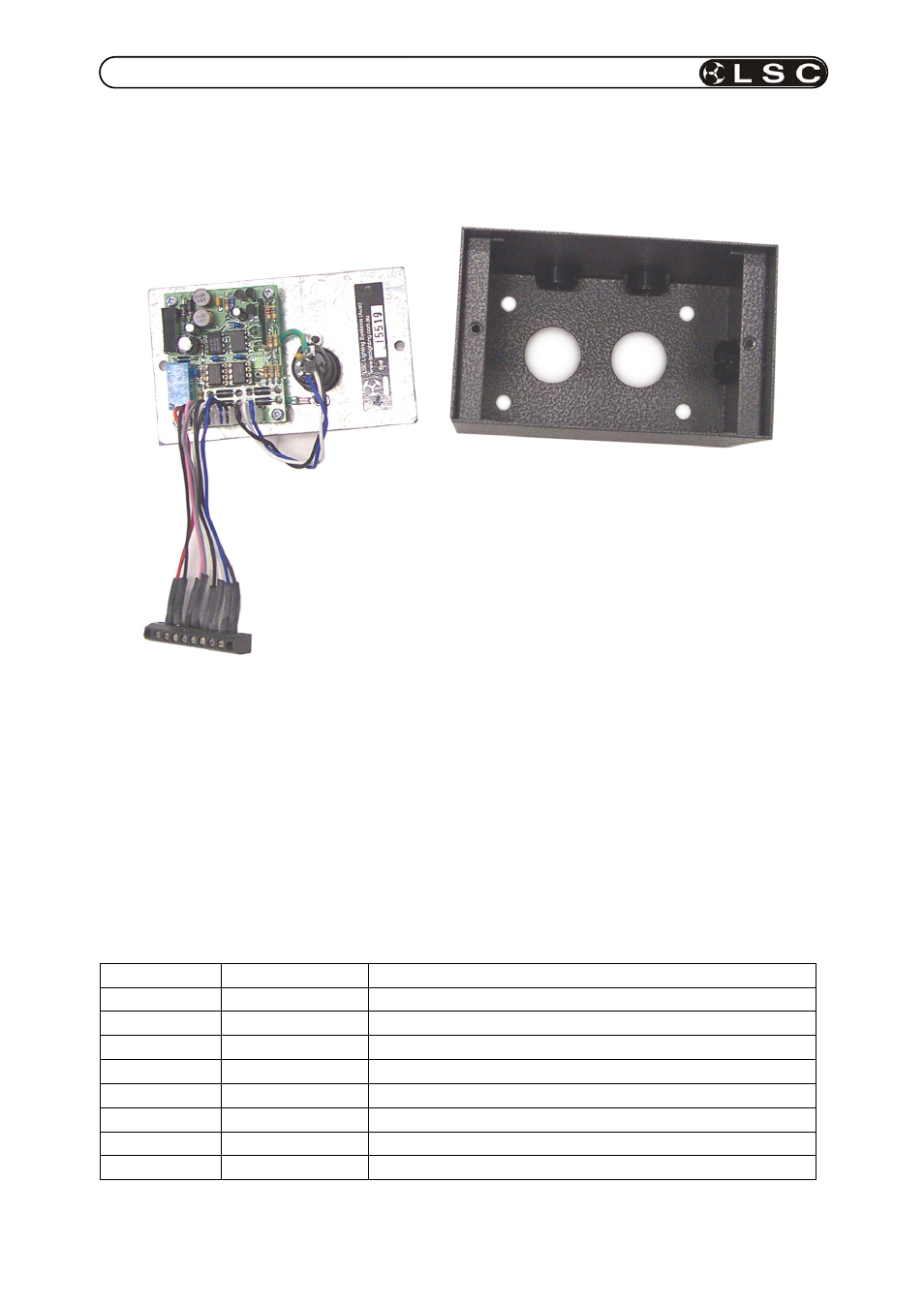
2.4 Isonode module
Each ISONODE module is supplied inside a metal installation housing that contains the
internal electronics. The picture below shows a disassembled ISONODE module.
ISOnode installation procedure.
1. Remove the two screws located on the front panel.
2. Separate the front panel and associated electronics from the installation housing (as
shown above).
3. Locate the installation housing in the desired location and secure it using the four mounting
holes located at the back of the housing. Four conduit holes are provided in the
installation housing.
4. Connect the DMX512 data and power input wiring to the screw terminal wiring strip as
detailed in table 3 below.
5.
Replace the front panel electronics into the metal housing and secure with the two screws.
Table 3 - Isonode DMX512 screw terminal wiring detail.
Terminal
Color
Signal Description
1 RED
+24VDC
Power
2
BLACK
Power supply ground
3
WHITE
DMX A + output
4
BLUE
DMX A - output
5
BLACK
COM A
6
YELLOW
DMX A + input
7
VIOLET
DMX A - input
8 ORANGE
COM
A
ISOnode installation housing
ISOnode front
Panel
Screw terminal wiring strip