Mount20, Projector mount, Mportant safety instructions – Marantz MOUNT20BL User Manual
Page 2: Warning, Installation instructions
MOUNT20
PROJECTOR MOUNT
INSTALLATION INSTRUCTIONS
I
MPORTANT SAFETY INSTRUCTIONS
READ BEFORE INSTALLING EQUIPMENT
This product was designed and manufactured to meet strict
quality and safety standards. There are, however, some
installation and operation precautions which you should be
particularly aware of.
1. Read instructions - All the safety and operating instructions
should be read before the product is operate
d.
2. Retain instructions - The safety and operating instructions
should be retained for future reference.
3. Heed warnings - All warnings on the product and in the
operating instructions should be adhered to.
4. Follow instructions - All installation instructions should
be followed.
5. Use only the parts provided with the mount, along with any
parts (commercially available) that are specified in this manual.
6. Do not modify the mount or the parts provided with the mount.
7. Do not use damaged parts. if any parts become damaged,
contact your dealer.
8. All bolts and screws must be tightened securely.
9. Make sure not to block any ventilation openings when installing
the projector.
11. Once the projector is installed, safety checks should be conducted
on a regular basis.
10. Special techniques and experience are required when installing
the projector with this mount. Contact your dealer to install the
projector for you.
Warning
Hardware List
Adjustment Ranges and Load Allowances
The ceiling should be capable of supporting a weight
of at least five (5) times the projector(s) weight.
If it cannot, the ceiling must be reinforced. Proper
installation procedure by qualified personnel as outlined
in the installation instructions must be adhered to.
Failure to do so could result in serious personal injury.
Step 1
Step 2
Figure 2
Figure 1
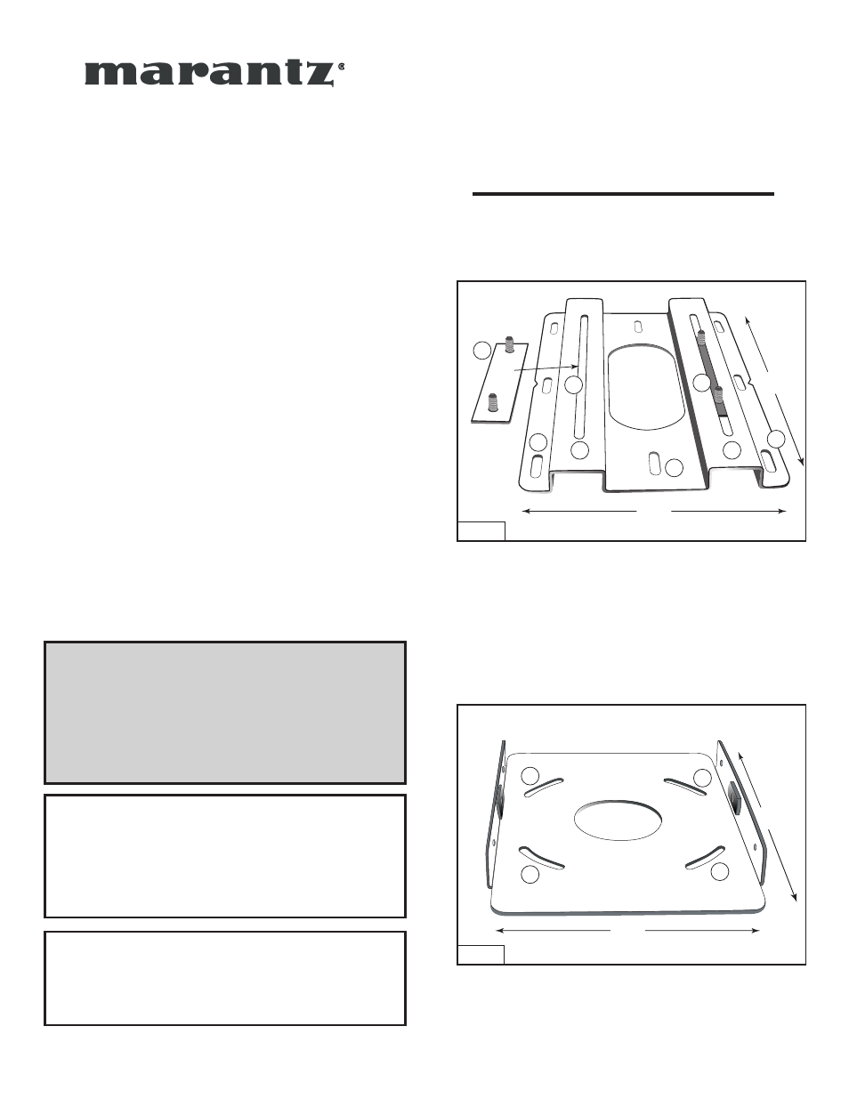
1
2
3
3
4
3
3
3
3
2
Wire
Access
14"
8 5/8"
Base Plate Connectors #1
Projector Mount Ceiling Plate 1
Plate 1
Plate 2
Base Plate Connectors #1 and Projector Mount Ceiling
Plate 1 with ceiling mounting holes #2.
Horizontal Adjustment Plate 2 (Base Plate Connector
Holes #3).
2
Ceiling Wire
Access
7 5/8"
10 5/8"
Insert Base Plate connectors #1 into the lateral positioning slots
#
3 as shown in #4 from the underside of Plate 1. The lateral positioning
slots will give you 2 1/4" inches of lateral adjustment for projector
alignment.
4
Base plate connector holes
#
3 provide 15 degrees of horizontal
rotation adjustment.
Attach horizontal adjustment Plate 2 to projector mount ceiling
Plate 1 using the four (4) 3/8" (inch) nuts and washers provided.
1. Four (4) 3/8 (inch) nuts
2. Four (4) 3/8 (inch) flat washers
3. Two (2) 8 (mm) screws
4. Eleven (11) 6 (mm) screws
5. Eight (8) 6 (mm) rubber washers
6. One (1) Ceiling Mount #1
7. Two (2) Base Plate Connectors
8. One (1) Horizontal Tilt Plate #2
9. One (1) Horizontal Tilt Plate #3
10. One (1) Projector Plate #4
Horizontal Tilt (yaw)
+/- 10 degrees
Vertical Tilt (tilt)
+/- 20 degrees
Rotation
+/- 15 degrees
Lateral Shift
+/- 2
1/4
inches
Maximum Load Allowance
450 Lbs.