Mathey Dearman CGM Cold Cutting System User Manual
Page 12
12
HYDRAULIC MACHINE - Join the Machine to a Hydraulic Power Supply having the properties mentioned in Section
2. The Hydraulic CGM-1 is powered by a closed oil circuit Hydraulic Power Supply having a 1/2" pressure (outlet) port
and 3/4" return (inlet) port. The use of a Hydraulic Power Supply smaller than that specified in Section 2 will
significantly hinder performance and may damage the CGM.
A. If Hydraulic Hoses longer than 15 meters (50 foot) are required, the hose diameters should be increased accordingly
to insure the CGM receives an adequate hydraulic flow and pressure.
B. Check the rotation of the Cutter Blades to insure the Hydraulic Power Supply is connected to the CGM-1 properly.
The rotation of the Cutter Blades is clockwise as shown in Figure 1.
C. The Hydraulic Model CGM-1 requires a small air compressor to operate the Automatic Double Mist Lubrication
System if installed.
D. Connect the Double Mist Lubrication System to the Coolant Container. Use a synthetic coolant oil type BIO/42 EP
or similar is recommended.
E. Turn the “Start / Stop Control” to the ON Position.
F. Slowly open Blade Speed Control counterclockwise until the rotational speed reaches about
71 – 76 revolutions per minute. Check the rotation of the Severing and Beveling Blades to make sure they are
turning clockwise.
5.2 SETTING GUIDE-WHEELS FOR THE PIPE DIAMETER TO BE CUT.
Figure 2 of Section 3 shows the different wheel positions for a variety of pipe diameters. Lift the machine and verify the
Wheel Holders holding the Machine Wheel are attached in the correct slots of the machine chassis for the diameter of
pipe to be cut.
Proceed as follows if Wheel Holders require position change due to change of pipe size.
A. Remove the four (4) Socket Head Cap Screws from the Wheel Holders that hold the Wheel Assemblies with the
supplied Hexagon Bit Socket for 16mm and Elbow Wrench with Bayonet that is furnished with machine.
B. Remove all metal chips and other debris from the Wheel Supports and slots in the bottom of the CGM Chassis.
C. Fit the Wheel Supports in the proper slot in the CGM Chassis for the diameter being cut and install the Four (4)
Socket Head Cap Screws.
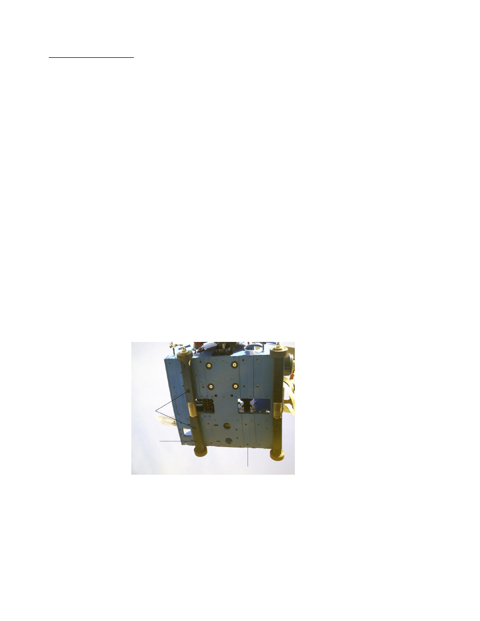
Figure 4: View of underside of CGM showing different Wheel positions.
5.3 HOW TO LENGTHEN AND SHORTEN THE DRIVE CHAIN
From Figure 2 of the Section 3, select the correct Drive-Chain length for the pipe diameter to be cut. If the 4 Mesh Chain
requires adjustment due to pipe size variance proceed as follows:
Socket
Head
Cap Screws
Wheel
Support
One of Six (6) Wheel Positions