Connecting to the a/d board, Signal cable, Cabling – Measurement Computing CIO-EXP32 User Manual
Page 10
CIO-EXP32 User's Guide
Installing the CIO-EXP32
Connecting to the A/D board
There are two 37-pin D type connectors on the CIO-EXP32 — P1 and P2. They are wired 1:1. Connector P1 is
labeled
NEXT EXP
, and is provided to daisy chain additional CIO-EXP32 boards. Use a C37FF-x cable to daisy
chain the CIO-EXP32 boards together. Do not exceed 50 feet in length.
Signals may be connected from the CIO-EXP32 board to the A/D board through one of two types of cables. The
cable used depends upon the type of A/D board you are connecting to. The table below lists the CIO-EXP32
board's connectors and compatible cables.
Board connector, cables, and accessory equipment
Connector type
P1 and P2: 37-pin D type connector
Compatible cables with connector P1
C37FF-x (connecting to additional CIO-EXP32 boards)
Compatible cables with connector P2
C37FF-x (connecting to a DAS08 board)
C-EXP2DAS16-10 (connecting to a DAS16 board)
Signal cable
The CIO-EXP32 signal connector is nearly a mirror of the CIO-DAS08 signal cable.
NC / LLGND 19
LLGND / Output 18
Output 9 17
Output 10 16
Output 11 15
Output 12 14
Output 13 13
Output 14 12
Output 15 11
MUX Addr 4 10
MUX Addr 3 9
MUX Addr 2 8
MUX Addr 1 7
NC 6
NC 5
NC 4
NC 3
NC 2
+12V PC Bus 1
37 Output 0
36 Output 1
35 Output 2
34 Output 3
33 Output 4
32 Output 5
31 Output 6
30 Output 7
29 +5V
28 Power GND
27 NC
26 NC
25 NC
24 NC
23 NC
22 NC
21 NC
20 -12V PC Bus
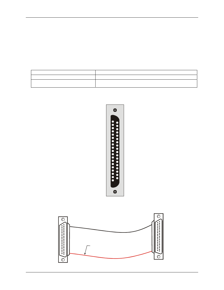
Figure 1. Connector P2/P1
Cabling
19
37
1
20
19
37
1
20
The red stripe
identifies pin # 1
Figure 2. C37FF-x cable
10