Channel selection for the das08 family, Channel selection for the das16 family, Exp gain – Measurement Computing CIO-EXP32 User Manual
Page 15
CIO-EXP32 User's Guide
Installing the CIO-EXP32
The CIO-EXP32 also has a semiconductor temperature sensor on board to measure the temperature of the board
in the region of the screw terminals. The temperature at the screw terminals is needed when thermocouples are
used with the CIO-EXP32. The temperature at the screw terminals is called the Cold Junction temperature, and
is needed to accurately calculate thermocouple temperature. This is known as Cold Junction Compensation.
When a CIO-EXP32 channel is used with a thermocouple, install the
CJC OUTPUT TO DAS
jumper in the
desired channel location. If you are not using thermocouples, do not install it.
Select the A/D board channel to connect the multiplexed analog output to using the jumpers labeled
EXP
OUTPUT TO DAS
.
Channels 0-15 are connected by default to A/D board channel 0. Channels 16-31 are connected by default
to A/D board channel 1.
Select the A/D board channel to connect the CJC output to (if required) using the jumpers labeled
CJC
OUTPUT TO DAS
.
CIO-EXP CJC is connected by default to A/D channel 7.
Channel selection for the DAS08 family
The DAS08 family of boards has eight channels of input, so only CIO-EXP32 jumper positions 0-7 are valid.
Many boards in the DAS08 family of boards have single-ended inputs, which is the correct type to connect to a
CIO-EXP32. If the inputs on the board type you are using are differential, they must be converted to single-
ended inputs (refer to the hardware user's manual supplied with your A/D board for more information).
You can connect up to eight banks of CIO-EXP32 inputs to a DAS08 series board, for a total of 128 inputs.
Channel selection for the DAS16 family
The CIO-EXP32 jumper positions 0-7 and 8-15 can be used with the CIO-DAS16. You can connect up to
16 banks of CIO-EXP32 inputs to a DAS16 series board, for a total of 256 inputs.
Most of the DAS16 family of A/D is switch-selectable for either 8 differential or 16 single-ended channels. Set
the switch for 16-channel, single-ended mode.
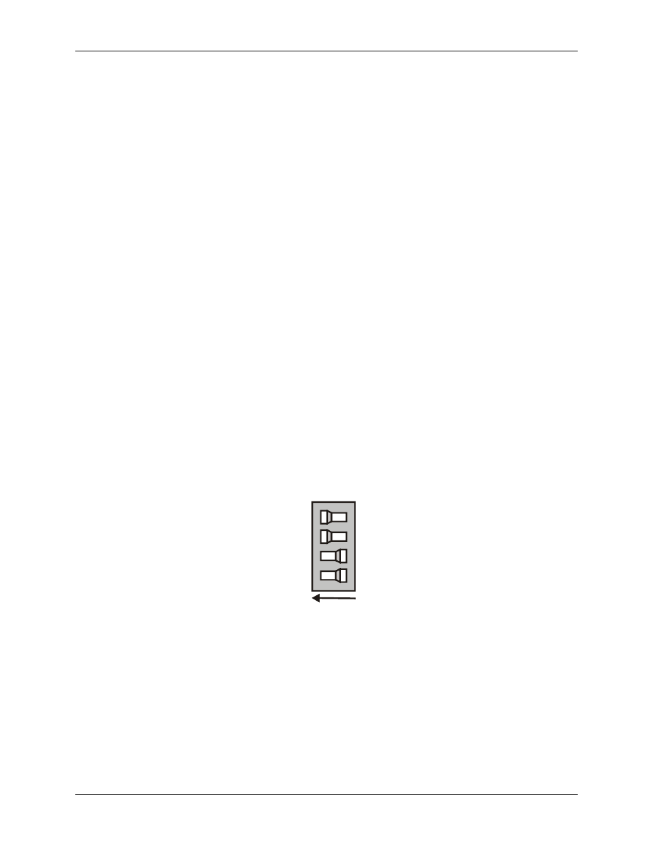
EXP Gain
The CIO-EXP32 has two banks of four DIP switches (
S1
and
S2
) that control the gain of the differential
amplifier.
shows a typical switch.
Figure 8. Gain switch
4
3
2
1
x500
x200
x100
x10
ON = left
The gain associated with a switch is 'ON' when the switch is to the left, and 'OFF' when the switch is to the
right. The gains are additive, so a total of 16 different gains are possible. The board is shipped with all switches
off (gain =1). The switch shown in Figu
is configured for a gain of 700 (500 + 200).
For most thermocouple applications, the gain should be set to at least 100. Refer to the section
on page 20 for data on setting optimum amplifier gains when using thermocouples.
For most other applications, the gain should be set to result in output signal levels as close to ±5V or ±10V
(depending on the range setting on the A/D board) as possible.
15