Power source, External +5 v pc power connections – Measurement Computing CIO-EXP32 User Manual
Page 13
CIO-EXP32 User's Guide
Installing the CIO-EXP32
Power source
You can supply +5V DC power to the via the 37-conductor cable from the A/D board in the PC (internal), or via
a separate optional power cable connected directly to the PC power supply (external). The internal method is
adequate for powering up to two CIO-EXP32 boards. Supply external power (connect the C-PCPOWER-10
power cable) when:
More than two CIO-EXP32 boards are used with one A/D board.
The A/D board in use does not supply +5V to its connector
Configure the CIO-EXP32 board’s power source with switch
S3
for either internal or external power. Figure 4
shows this switch configured in both positions.
+5V power from the
PC via 37 conductor
signal cable
+5V power from the
PC via 2 conductor
optional
ower cable
C-PCPOWER-10
p
S3
+5V
EXT
INT
Internal power
External power
S3
+5V
EXT
INT
Figure 4. Power source-select switch
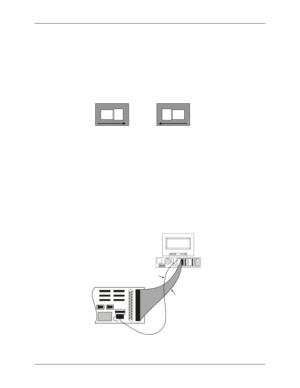
External +5 V PC power connections
You can power the CIO-EXP32 with your computer’s +5V power supply using the optional
C-PCPOWER-10
cord. Each end of the cable has a keyed Molex
®
type connector. To connect to your computer’s power
connectors, do the following:
1.
2.
Turn off power to the computer and remove the cover.
Connect the black cable with the white Molex
®
type connectors to one of the unused PC expansion power
connectors from the PC power supply. They are keyed, so the cable will plug into the expansion connector
easily when they are aligned (see
Figure 5. External power cable installation
DC/DC
Signal cable
P2 to CIO-DAS08
analog board
Power cable
J3 to PC Power Supply
Personal Computer
CIO-EXP32
3.
Run the power cable out the back of the computer through an expansion slot or other opening and replace
the cover on the computer.
13