Digital i/o, Power outputs, Ground terminals – Measurement Computing USB-5201 User Manual
Page 11: Thermocouple connections, Wiring configuration
USB-5201 User's Guide
Sensor Connections
11
Digital I/O
You can connect up to eight digital I/O lines to the screw terminals labeled
DIO0
to
DIO7
. Each terminal is
software-configurable for input or output. If a digital bit is set up as an alarm, the bit is configured for output on
power-up, and assumes the state defined by the alarm configuration.
Power outputs
The two
+5V
output
terminals are isolated (500 VDC) from the USB +5V.
Caution! Each +5V terminal is an output. Do not connect to an external power supply to these terminals or
you may damage the USB-5201 and possibly the computer.
Ground terminals
The six analog ground terminals (
GND
) provide a common ground for the input channels and DIO bits and are
isolated (500 VDC) from the USB GND.
Thermocouple connections
A thermocouple consists of two dissimilar metals that are joined together at one end. When the junction of the
metals is heated or cooled, a voltage is produced that correlates to temperature.
The USB-5201 makes fully-differential thermocouple measurements without the need of ground-referencing
resistors. A 32-bit floating point value in either a voltage or temperature format is returned by software. An
open thermocouple detection feature is available for each analog input which automatically detects an open or
broken thermocouple.
Use InstaCal to select the thermocouple type (J, K, R, S, T, N, E, and B) and one or more sensor input channels
to connect the thermocouple.
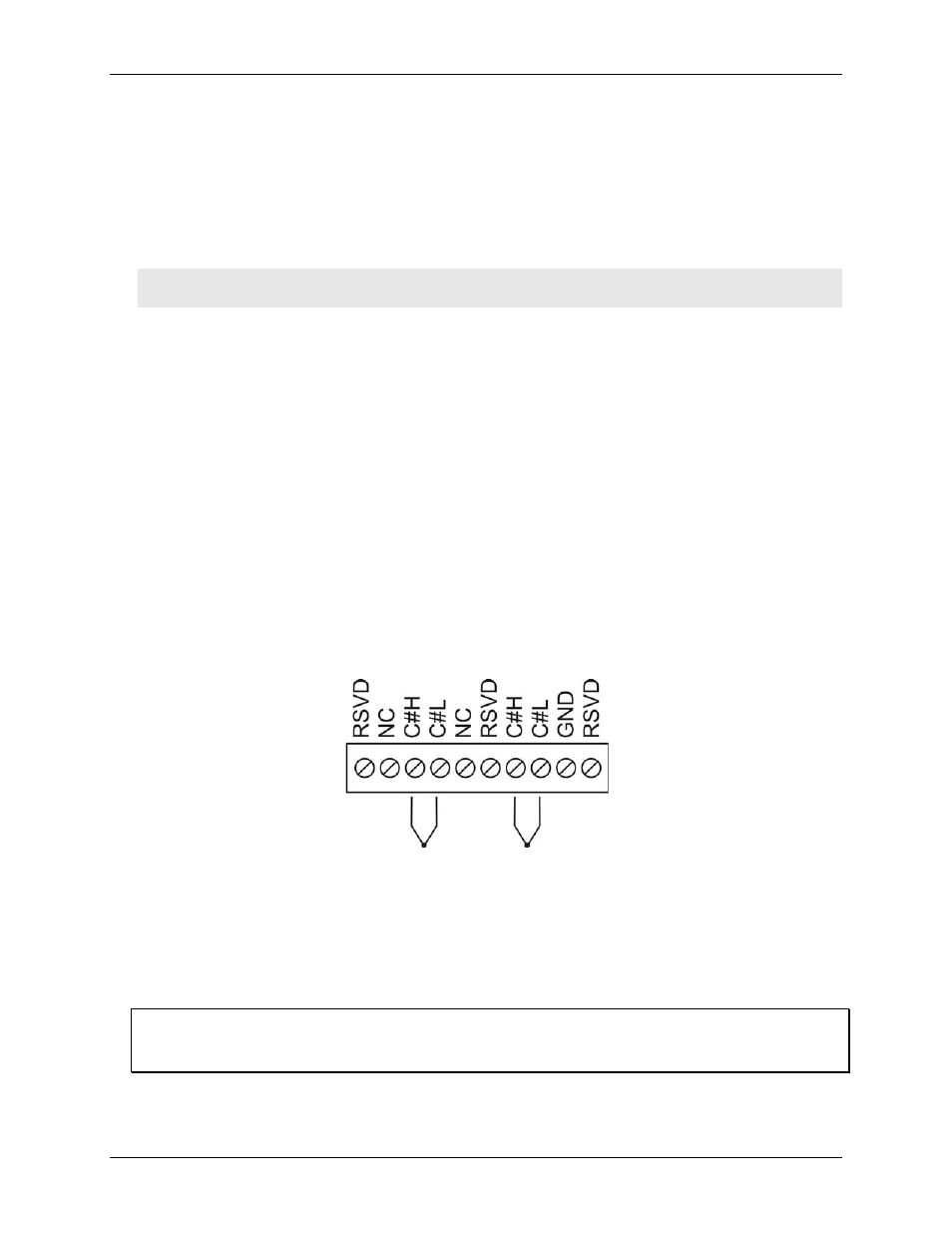
Wiring configuration
Connect the thermocouple to the USB-5201 using a differential configuration, as shown in Figure 3.
Figure 3. Typical thermocouple connection
Connect thermocouples to the USB-5201 such that they are floating with respect to GND. The ground pins are
isolated from earth ground, so you can connect thermocouple sensors to voltages referenced to earth ground as
long as the isolation between the GND pins and earth ground is maintained.
When thermocouples are attached to conductive surfaces, the voltage differential between multiple
thermocouples must remain within ±1.4 V. For best results, you should use insulated or ungrounded
thermocouples when possible.
Maximum input voltage between analog input and ground
The absolute maximum input voltage between an analog input and the isolated GND pins is ±25 VDC when the
device is powered on, and ±40 VDC when the device is powered off.
If you need to increase the length of your thermocouple, use the same type of thermocouple wires to minimize
the error introduced by thermal EMFs.