Digital i/o connections, Configuring the dio channels to generate alarms – Measurement Computing USB-5201 User Manual
Page 12
USB-5201 User's Guide
Sensor Connections
12
Digital I/O connections
You can connect up to eight digital I/O lines to the screw terminals labeled
DIO0
to
DIO7
. You can configure
each digital bit for either input or output. All digital I/O lines are pulled up to +5 V with a 47
kΩ resistor
(default). You can request the factory to configure the resistor for pull-down to ground, if desired.
Caution! If a digital bit is set up as an alarm, the bit will be configured for output on power-up, and assume
the state defined by the alarm configuration.
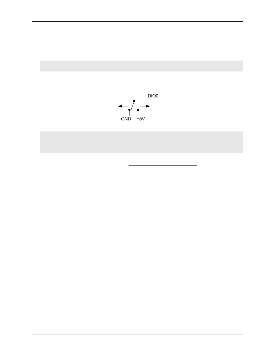
When you configure the digital bits for input, you can use the USB-5201 digital I/O terminals to detect the state
of any TTL-level input. Refer to the schematic shown in Figure 4. If you set the switch to the +5 V input, DIO0
reads TRUE (1). If you move the switch to GND, DIO0 reads FALSE (0).
Figure 4. Schematic showing switch detection by digital channel DIO0
Caution! All ground pins are common and are isolated from earth ground. If a connection is made to earth
ground when using digital I/O and conductive thermocouples, the thermocouples are no longer
isolated. In this case, thermocouples must not be connected to any conductive surfaces that may be
referenced to earth ground
For general information regarding digital signal connections and digital I/O techniques, refer to the Guide to
Signal Connections (available on our web sit
Configuring the DIO channels to generate alarms
The USB-5201 features eight independent temperature alarms. All alarm options are software configurable.
When a digital bit is configured as an alarm, that bit is configured as an output on the next power cycle and
assumes the state defined by the alarm configuration.
Each alarm controls an associated digital I/O channel as an alarm output. The input to each alarm is one of the
temperature input channels. You set up the temperature conditions to activate an alarm, and the output state of
the channel (active high or low) when activated. When an alarm is activated, its associated DIO channel is
driven to the output state specified.
The alarm configurations are stored in non-volatile memory and are loaded on power up. The temperature
alarms function both in data logging mode and while attached to the USB port on a computer.