External components, Screw terminals, Usb connector – Measurement Computing USB-5201 User Manual
Page 14
USB-5201 User's Guide
Functional Details
14
External components
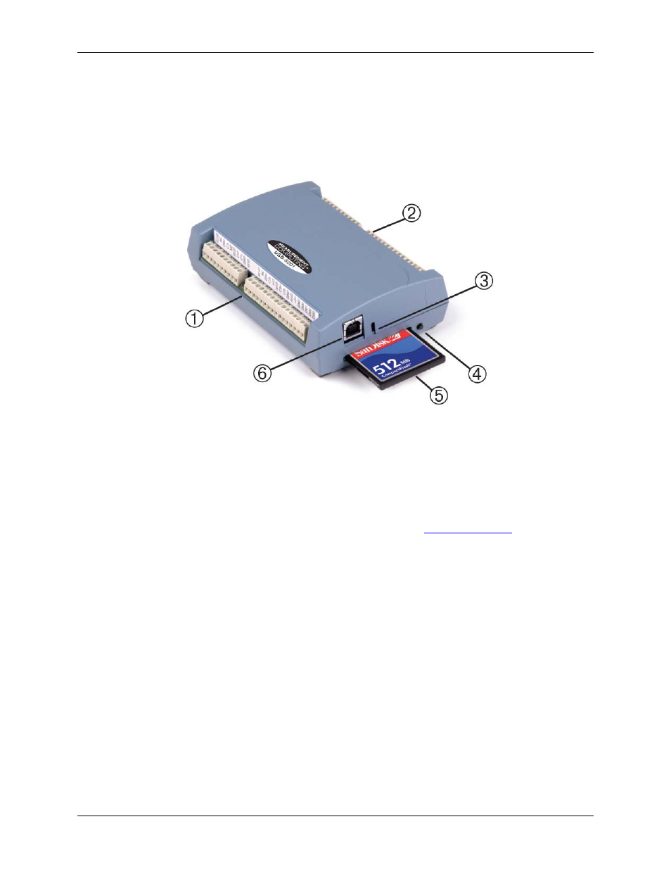
The USB-5201 has the following external components, as shown in Figure 5.
Screw terminals
USB connector
LED
CompactFlash slot with memory card
1
Screw terminal pins 1 to 26
4
Data logging button
2
Screw terminal pins 27 to 52
5
CompactFlash memory card slot (with card)
3
LED
6
USB connector
Figure 5. External component locations
Screw terminals
The device's four banks of screw terminals are for connecting temperature sensors and digital I/O lines. These
terminals also provide ground and power output connections. Refer to the
terminal descriptions.
USB connector
When not logging data, connect the USB cable to a USB port on your computer or to an external USB hub that
is connected to your computer. When connected to an active USB bus, the device's USB connector provides
+5 V power and communication. The voltage supplied through the USB connector is system-dependent, and
may be less than 5 V. No external power supply is required.
Due to processing limitations, you cannot log data when the device is attached to an active USB bus. For data
logging operations, connect the device's USB connector to the external power supply.
LED
The LED uses up to 5 mA of current. The function of the LED varies according to whether the USB-5201 is
connected to an active USB port, or when the device is logging data and connected to the external power
supply.
Refer to the following table for the function of the LED when the device is connected to an active USB port and
not logging data.