Accuracy, Thermocouple measurement accuracy – Measurement Computing USB-5201 User Manual
Page 19
USB-5201 User's Guide
Specifications
19
Accuracy
Thermocouple specifications include linearization, cold-junction compensation and system noise. These specs
are for one year, or 3000 operating hours, whichever comes first and for operation of the device between 15 °C
and 35 °C. For measurements outside this range, add ±0.5 °C to the maximum error shown.
There are CJC sensors on each side of the device. The accuracy listed in Table 3 assumes the screw terminals
are at the same temperature as the CJC sensor. Errors shown do not include inherent thermocouple error.
Contact your thermocouple supplier for details on the actual thermocouple error.
Thermocouples must be connected to the device such that they are floating with respect to GND (pins 9, 19, 28,
38). The device GND pins are isolated from earth ground, so connecting thermocouple sensors to voltages
referenced to earth ground is permissible as long as the isolation between the GND pins and earth ground is
maintained.
When thermocouples are attached to conductive surfaces, the voltage differential between multiple
thermocouples must remain within ±1.4 V. For best results, MCC recommends using ungrounded or insulated
thermocouples when possible.
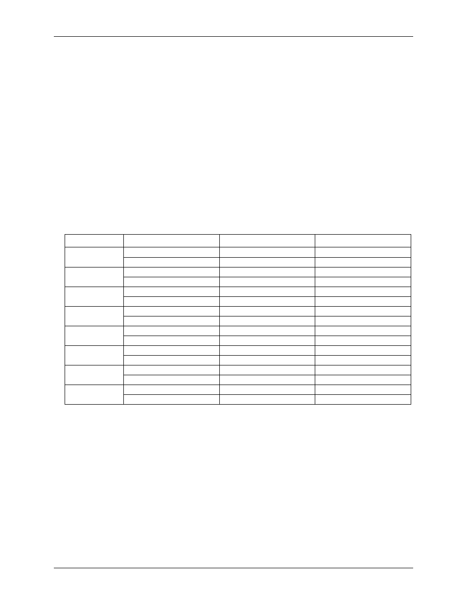
Thermocouple measurement accuracy
Table 3. Thermocouple accuracy specifications, including CJC measurement error
Sensor type
Maximum error (°C)
Typical error (°C)
Temperature range (°C)
J
±1.499
±0.507
–210 to 0
±0.643
±0.312
0 to 1200
K
±1.761
±0.538
–210 to 0
±0.691
±0.345
0 to 1372
S
±2.491
±0.648
–50 to 250
±1.841
±0.399
250 to 1768.1
R
±2.653
±0.650
–50 to 250
±1.070
±0.358
250 to 1768.1
B
±1.779
±0.581
250 to 700
±0.912
±0.369
700 to 1820
E
±1.471
±0.462
–200 to 0
±0.639
±0.245
0 to 1000
T
±1.717
±0.514
–200 to 0
±0.713
±0.256
0 to 600
N
±1.969
±0.502
–200 to 0
±0.769
±0.272
0 to 1300