Measurement Computing USB-5201 User Manual
Page 25
USB-5201 User's Guide
Specifications
25
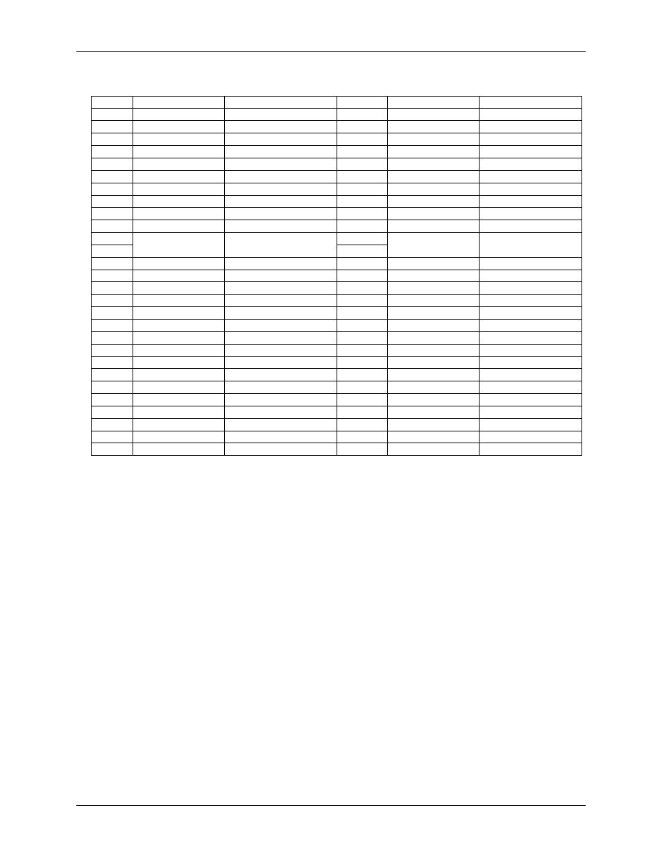
Table 17. Screw terminal pinout
Pin
Signal Name
Pin Description
Pin
Signal Name
Pin Description
1
RSVD
Reserved, do not use
27
RSVD
Reserved, do not use
2
NC
No connection
28
GND
Ground
3
C0H
CH0 sensor input (+)
29
C7L
CH7 sensor input (–)
4
C0L
CH0 sensor input (–)
30
C7H
CH7 sensor input (+)
5
NC
No connection
31
RSVD
Reserved, do not use
6
RSVD
Reserved, do not use
32
NC
No connection
7
C1H
CH1 sensor input (+)
33
C6L
CH6 sensor input (–)
8
C1L
CH1 sensor input (–)
34
C6H
CH6 sensor input (+)
9
GND
Ground
35
NC
No connection
10
RSVD
Reserved, do not use
36
RSVD
Reserved, do not use
CJC sensor
CJC sensor
11
RSVD
Reserved, do not use
37
RSVD
Reserved, do not use
12
NC
No connection
38
GND
Ground
13
C2H
CH2 sensor input (+)
39
C5L
CH5 sensor input (–)
14
C2L
CH2 sensor input (–)
40
C5H
CH5 sensor input (+)
15
NC
No connection
41
RSVD
Reserved, do not use
16
RSVD
Reserved, do not use
42
NC
No connection
17
C3H
CH3 sensor input (+)
43
C4L
CH4 sensor input (–)
18
C3L
CH3 sensor input (–)
44
C4H
CH4 sensor input (+)
19
GND
Ground
45
NC
No connection
20
RSVD
Reserved, do not use
46
RSVD
Reserved, do not use
21
+5V
+5V output
47
+5V
+5V output
22
GND
Ground
48
GND
Ground
23
DIO0
DIO channel 0
49
DIO7
DIO channel 7
24
DIO1
DIO channel 1
50
DIO6
DIO channel 6
25
DIO2
DIO channel 2
51
DIO5
DIO channel 5
26
DIO3
DIO channel 0
52
DIO4
DIO channel 4