Default settings, Ieee 488 bus address selection, Mode selection – Measurement Computing DAC488 v.1 User Manual
Page 13: Analog output ports, Ode selection…… 7, Tput ports…… 7
DAC488 User’s Manual
DAC488 Setup 7
Default Settings
The DAC488 unit may be operated from either 110 VAC or 220 VAC.
The operating voltage is set by an internal switch. The factory set
operating voltage appears on the label placed over the power jack on the
rear panel. To change the operating voltage, see section Line Voltage
Selection in Chapter 3.
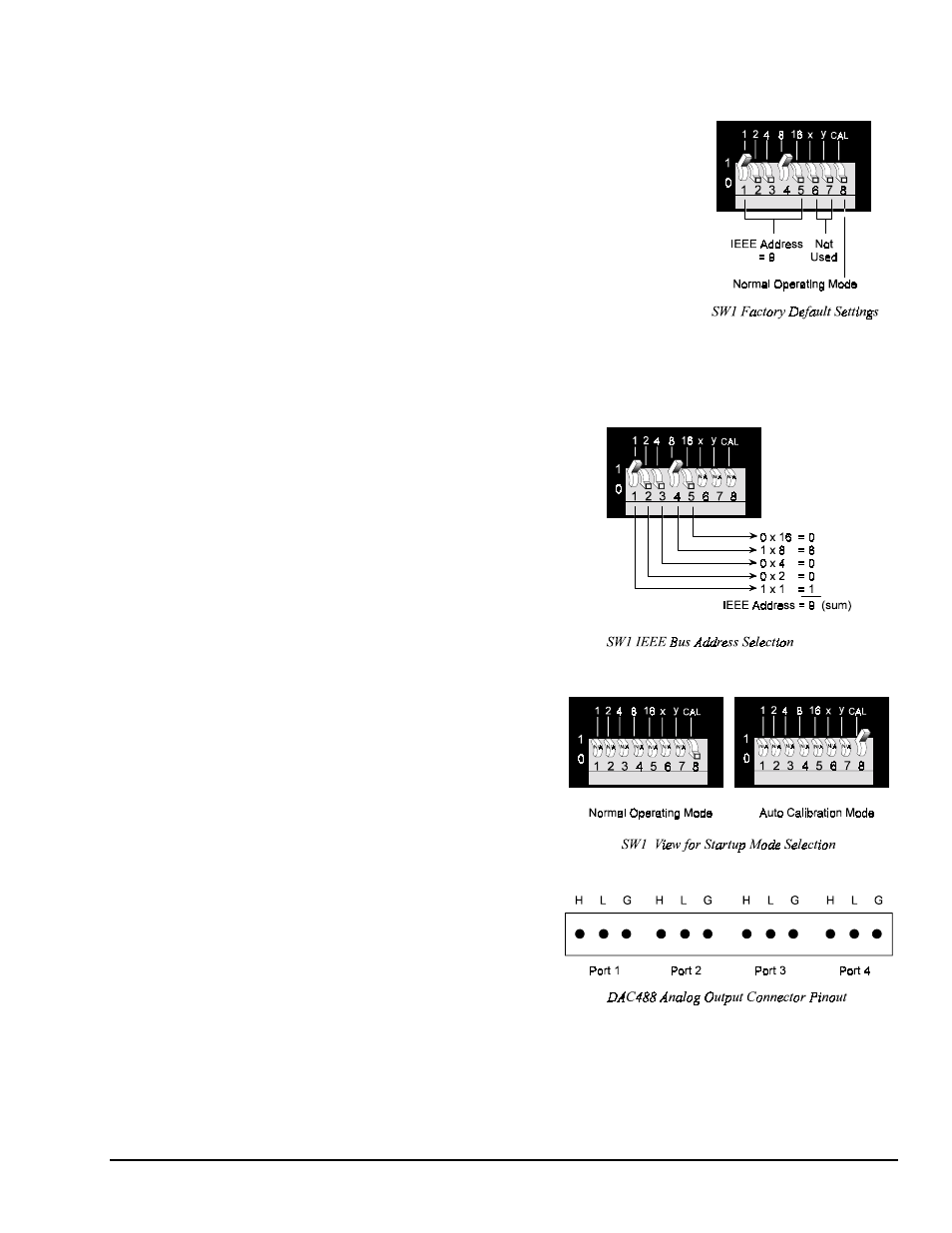
The DAC488 unit has one 8-microswitch DIP switch (SW1) accessible
from the rear panel. This DIP switch determines the IEEE 488 bus
address and its operating mode. The switch is read only when the unit is
powered on and should be set prior to applying power. The figure
illustrates the factory default for the DIP microswitch settings. To
modify the default settings, disconnect the power cord from the AC line
and change the microswitch settings using a small screwdriver. The
enclosure does not need to be opened to change the DIP microswitch
settings.
IEEE 488 Bus Address Selection
The IEEE 488 bus address is set by positioning the
rear-panel DIP microswitches 1 through 5. The
address can be set from 0 through 30 and is read
only at power on. The address is selected by
simple binary weighting with microswitch 1 being
the Least Significant Bit (LSB) and microswitch 5
the Most Significant Bit (MSB). The factory
default setting is address 9, as shown in the
diagram. If address 31 is selected, it defaults to
address 30 because the IEEE 488 standard has
reserved address 31.
Mode Selection
The DAC488 can be operated in one of two modes:
Normal operating mode or automatic calibration
mode, which are selected by the rear-panel DIP
microswitch 8. The factory default setting for
microswitch 8 is normal operating mode, as shown
in the diagram.
Analog Output Ports
The DAC488 can be considered as multiple
isolated IEEE 488 to Analog Converters. The unit
occupies one IEEE 488 bus address. Each port has
a low (L), high (H), and ground (case ground) line.
The case ground line may be connected to the
shield of shielded cable if this type of cable is used
to carry the analog signals. The pinouts for all
analog ports are labeled on the rear panel of the
unit. Each analog output is capable of sourcing
and sinking a maximum current of 10 mA.