Control modes, Direct control mode, Indirect control mode – Measurement Computing DAC488 v.1 User Manual
Page 34: Stepped control mode, Ode…… 28, Ode……28
28 DAC488 Operation
DAC488 User’s Manual
Control Modes
Four modes of DAC port operation are available: Direct, Indirect, Stepped, and Waveform. Each port is
independent and may be operated in a different mode. The modes of operation are described below.
Direct Control Mode
Each of the DAC ports may be directly controlled from the IEEE 488 bus. In the Direct Control mode, a
DAC voltage is output upon receipt of the Execute (
X
) command. Direct control is accomplished by
selecting the DAC port, the range or autorange, specifying the DAC output voltage, and issuing the Execute
command.
One use of the Direct mode is to output voltages at one or more DAC ports directly under program control
from an IEEE controller. To output 4 volts on port 1 the following command string could be used:
PRINT#1,"OUTPUT09;C0 P1 A0 R2 V4 X"
In this example,
C0
selects Direct Control mode,
P1
selects port 1,
A0
disables Autoranging,
R2
selects the
±
5 Volt range and
V4
is the voltage to be output (4 volts). This command string causes the DAC488 to
output 4 volts at port 1.
Indirect Control Mode
Indirect control implies that the DAC output will change only when a trigger event occurs. Indirect control
is accomplished by selecting the DAC port, the range or autorange, specifying the DAC output voltage and
the desired trigger source. When the trigger event occurs, the programmed voltage will be output.
One use of the Indirect mode is to output voltages at one or more DAC ports upon the occurrence of a
trigger event. The command string shown below causes the DAC488 to output 7.5 volts at Port 2 upon
receipt of an external trigger signal.
PRINT#1,"OUTPUT09;C1 P1 Q1 A0 R2 V4 X"
In this example,
C1
selects the Indirect control mode,
P1
selects port 1,
Q1
enables port 1 to trigger on the
positive edge of an external trigger sense pulse,
A0
disables autoranging,
R2
selects the
±
5 Volt range and
V4
is the voltage to be output (4 volts).
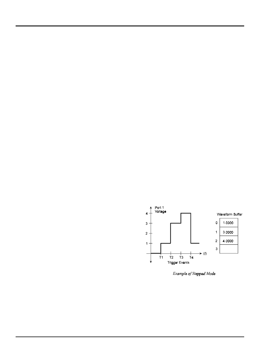
Stepped Control Mode
The Stepped control mode may be used to control
the DAC in a stepped manner. In this mode, a
sequence of DAC voltages are loaded into the
DAC488 internal buffer. After the voltages are
loaded into the buffer, the DAC output can then
be stepped through each of the values by using
any of the three trigger sources. When the last
voltage in the buffer is output, the DAC488 will
automatically return to the first location defined
by the Buffer Definition (
F
) command thereby
allowing the sequence to be repeated.
One application of Stepped mode may be to use
the DAC488 to output a series of test voltages
which may control another device. The example
shows how the DAC488 would be configured to
output the next voltage in a sequence of voltages
each time an external trigger is received.
In this example, the voltage at port 1 is stepped to the next value in the buffer each time an external trigger
is received. Each T on the graph represents a trigger event. The voltage sequence is 1 volt, 3 volts, 4 volts.