Automatic calibration procedure, Part i: connections & preparations, Libration procedure…… 47 – Measurement Computing DAC488 v.1 User Manual
Page 53
DAC488 User’s Manual
DAC488 Calibration 47
Automatic Calibration Procedure
Part I: Connections & Preparations
Fully automatic (or Stand-Alone) calibration of the DAC488 may be
performed by connecting the DAC488 to a Keithley Instruments 199
DMM/Scanner. In the automatic calibration mode, the DAC488 acts as a
bus controller. Automatic calibration requires the DAC488 to be
connected to a Keithley 199 DMM both on the IEEE 488 bus and with
the DAC ports connected to the scanner inputs using the calibration cable
wired as described in the following text. An optional IEEE printer may
also be connected on the bus and when calibration is finished the
DAC488 will print a calibration report. Any other device which functions
as a bus controller must be disconnected from the bus during the DAC488
auto-calibration.
The IEEE address of the 199 must be set to 26 and the address of the printer must be 5. The address of the
DAC488 is internally set to 0 regardless of the rear panel address switch settings.
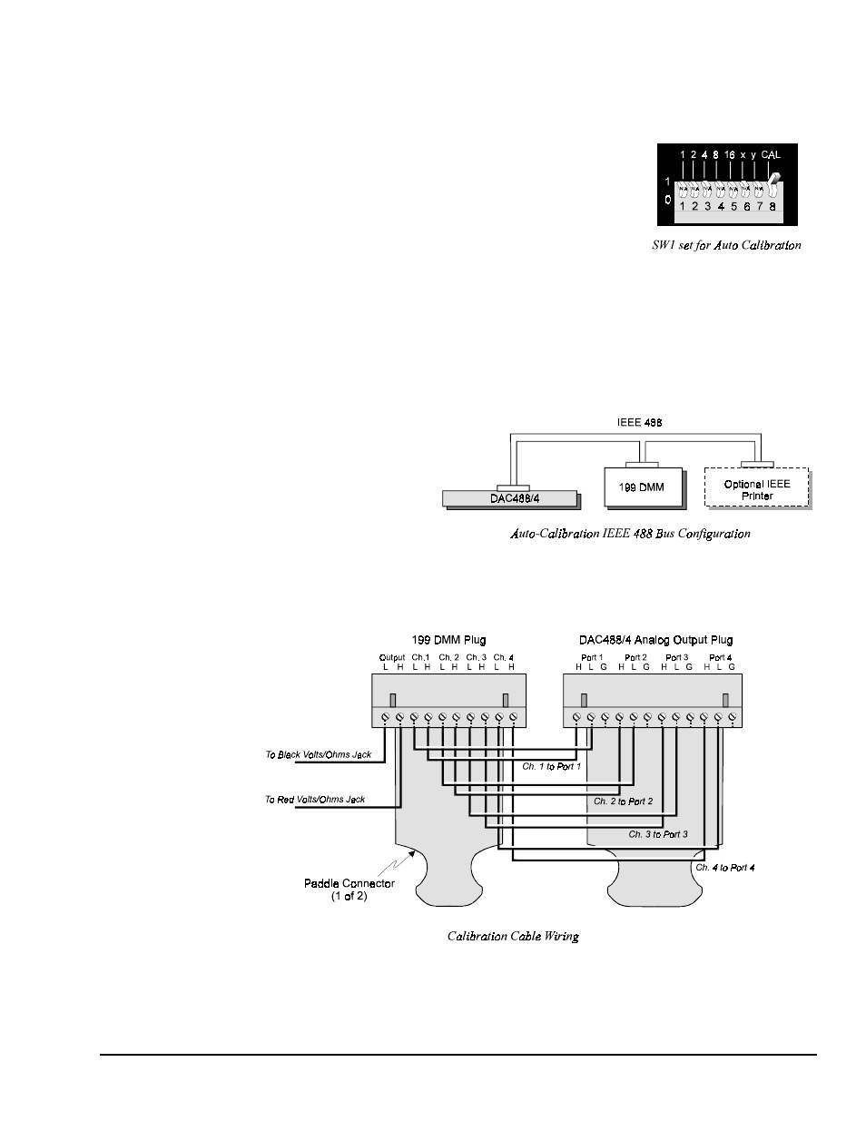
1. With the unit off, set the rear-panel DIP microswitch 8 in the up position to enable the automatic
calibration mode, as shown in the figure.
2. The Keithley Model 199 and
optional printer must then be
connected to the IEEE 488
connector on the DAC488 rear
panel, as shown below. Any other
IEEE controllers should be
disconnected from the IEEE bus.
3. You must now make a calibration cable using the analog connectors for the DAC488 and the 199.
Both connectors have screw terminals therefore no soldering is required. The wiring for this cable is
shown in the next diagram. If you are calibrating a DAC488/2, omit the wiring for ports 3 and 4.