F - buffer definition, F - buffer definition…… 66 – Measurement Computing DAC488 v.1 User Manual
Page 72
66 DAC488 Commands
DAC488 User’s Manual
F - Buffer Definition
TYPE
Port Command
SYNTAX
Fstart,
size
Defines the starting location and size of a buffer, where
start
and
size
are
each a value between 0 and 8191, such that their sum is less than 8192.
F?
Returns starting location and buffer size of most recently defined buffer
DESCRIPTION
The Buffer Definition command is used to create a buffer of voltage values for use in the Stepped (C2) or Waveform
(C3) Control modes. A buffer is defined by specifying the starting location and the buffer size. Any size buffer may be
defined, but the last location must be at a numerically higher location than the first location. More than one port may
share the same buffer if it is desired to output the same values at different ports simultaneously.
Note:
(1) The sum of start and size must be less than 8192. (2) The default start and size values for each port
are as follows:
Port
Def. Start
Def. Size
DAC488
1
0
1024
Both
2
1024
1024
Both
3
2048
1024
DAC488/4 only
4
3072
1024
DAC488/4 only
EXAMPLE
PRINT#1,"CLEAR09"
Line 1: Reset the DAC488.
PRINT#1,"OUTPUT09;C3 P1
F0,2 G1 N0 L0 I1 X"
Line 2: Select Waveform Control mode, select port 1, define a buffer with the
starting location=0 and size=2, enable port 1 to trigger on GET, set number
of cycles to continuous, set location pointer to 0 (first buffer location for the
port 2 buffer), set time interval between points to 1 millisecond.
PRINT#1,"OUTPUT09;B2,3 X
B2,-3 X"
Line 3: Set buffer location 0 to 3 volts, set buffer location 1 to -3 volts.
PRINT#1,"OUTPUT09;L0 X"
Line 4: Set location pointer back to 0 (first location for the port 1 buffer).
PRINT#1,"OUTPUT09;C3 P2
F10,2 G2 N0 L10 I2 X"
Line 5: Select Waveform Control mode, select port 2, define a buffer with
the starting location=10 and size=2, enable port 2 to trigger on GET, set
number of cycles to continuous, set location pointer to 10 (first location for
the port 2 buffer), set time interval between points to 2 milliseconds.
PRINT#1,"OUTPUT09;B2,3 X
B2,2 X"
Line 6: Set buffer location 10 to 3 volts set buffer location 11 to 2 volts.
PRINT#1,"OUTPUT09;L10 X"
Line 7: Set location pointer to 10 (first location for the port 2 buffer).
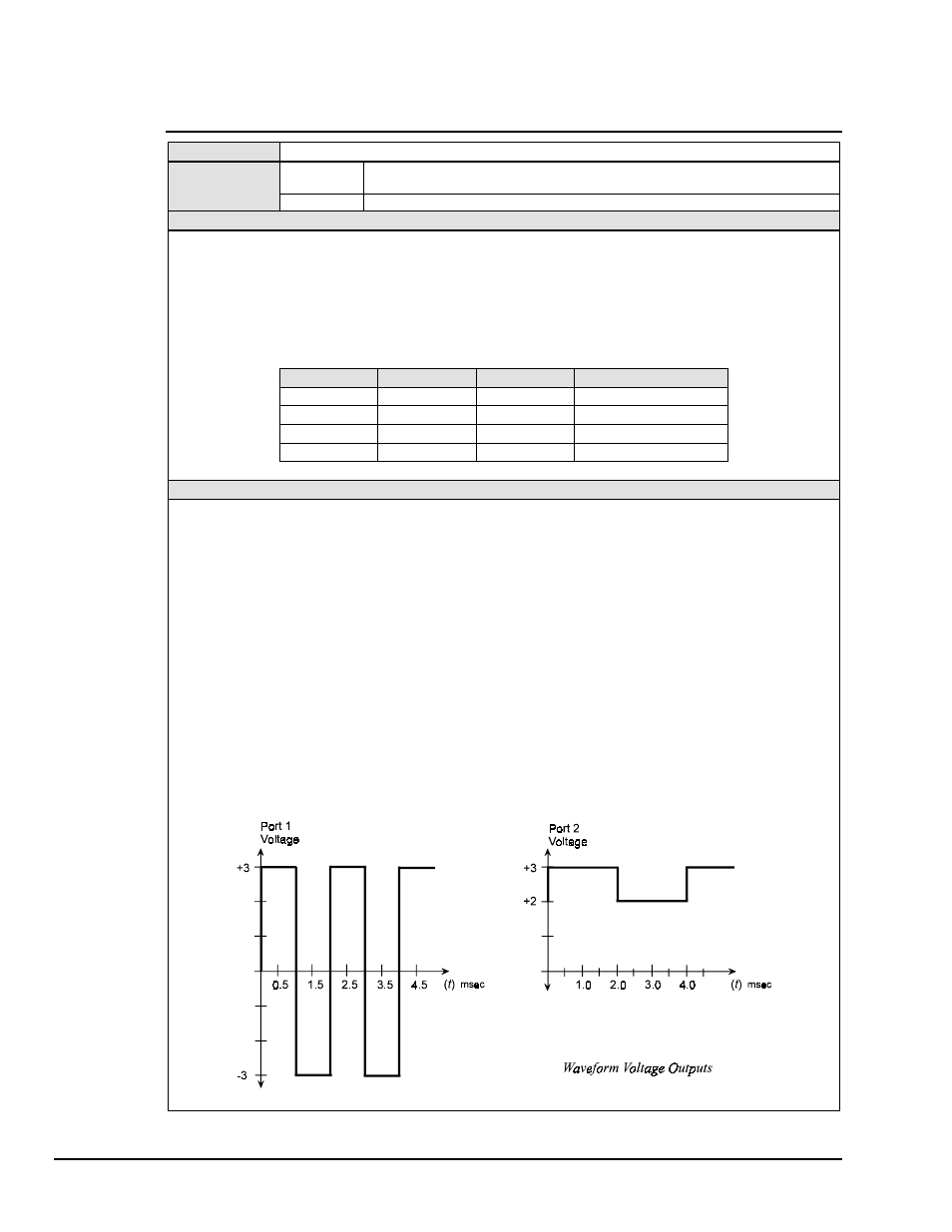
PRINT#1,"TRIGGER"
Line 8: Trigger the DAC488. The DAC488 will output the following
waveforms on ports 1 and 2.