External trigger/srq input, To configure the digital output lines, Warning – Measurement Computing DAC488 v.1 User Manual
Page 17
DAC488 User’s Manual
DAC488 Setup 11
External Trigger/SRQ Input
The External Trigger/SRQ input (Standard pin 18; CE pin 2) can be used to trigger the DAC488 once it has
been properly armed. The DAC488 can be programmed to trigger on a positive-going or negative-going
edge by using the External Trigger Mask (
Q
) command. Any TTL level signal may be used as a trigger
pulse. A trigger pulse may also be used to generate an SRQ by using the Service Request Mask (
M
)
command. The maximum rate at which the DAC488 can be triggered is 1 trigger pulse every 1 millisecond.
To Configure the Digital Output Lines
WARNING
WARNING
WARNING
WARNING
Service: This product contains no operator serviceable parts. Fuse replacement and
the changing of selected line voltage must be performed by qualified service personnel.
Never open the DAC488 case while it is connected to the AC line, or when analog
output terminals are connected to a device exceeding 60 VDC or 30 Vrms common
mode voltage!
CAUTION
CAUTION
CAUTION
CAUTION
Do not connect external high level devices to the digital output lines unless they have
first been configured for this purpose. Otherwise the interface may be damaged.
1. First, disconnect any cables from the
analog output terminals. Next,
disconnect the power cord from the
AC line and from the interface. Then
disconnect any other cables prior to
disassembly.
2. Place the interface on a flat surface.
Remove the six screws on top of the
case and remove the top cover.
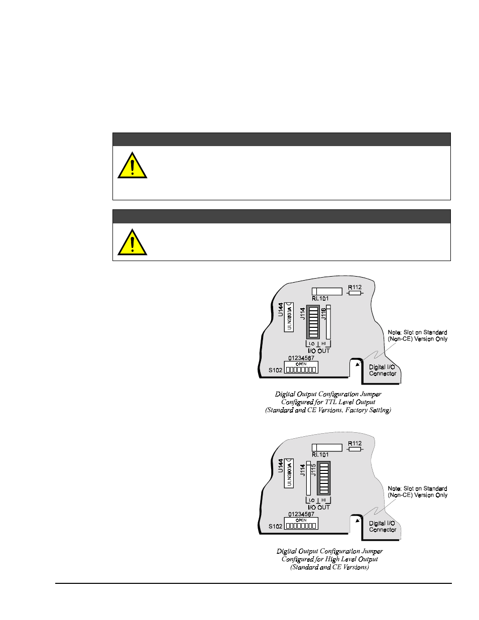
3. Located in front of the rear-panel DIP
switch (SW1) are three sockets and a
configuration jumper. This jumper is
factory set to configure the digital
output lines for low level TTL logic
levels, as shown in the figure.
4. To configure the digital output lines
as high voltage/high current outputs,
first remove the configuration jumper.
5. Next, reinsert it so that the center
socket is now connected to the right
socket, as shown in the second figure.
6. Once the jumper has been
repositioned for your particular
application, make note of the new
setting for later reference.
7. Carefully reassemble the unit.