Dynamics knee, Channelstrip user guide – Metric Halo ChannelStrip 2 User Manual
Page 16
ChannelStrip User Guide
12
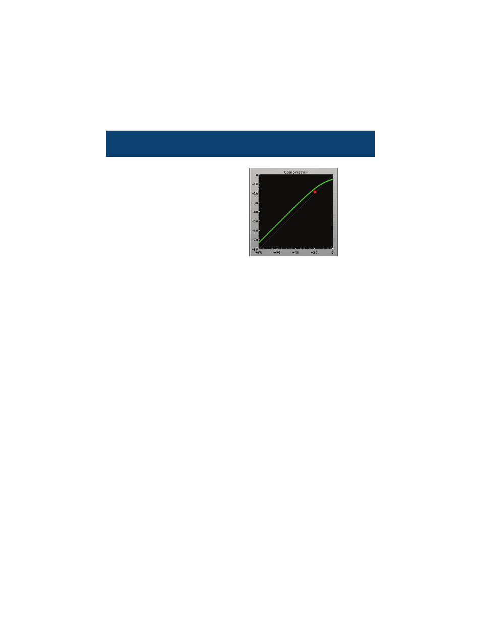
Dynamics Knee
ChannelStrip contains a
Dynamics Knee diagram for
each gate and each compres-
sor processing section. The
diagram provides feedback on
the response of the associ-
ated dynamics processor.
Both the horizontal and verti-
cal axes are calibrated in
dBFS. The horizontal axis cor-
responds to the input level
and the vertical axis repre-
sents the output level. The heavy line shows the quiescent dynamical
response of the associated processing block. This means that if you
sent in a sine wave at a given input level, the output level would be
equal to the level shown on the graph. When the processor is work-
ing with real dynamic signals, the graph is a good approximation of
the response when the attack is fast and the release is slow.
In most cases, however, the dynamic response of the processor will
not match its static response. In order to represent this, we have
included a “bouncing ball” meter for both the gate and the compres-
sor. This metering is shown as a red square that is overlaid on the
knee diagram. The red square is placed so its horizontal position is
equal to the instantaneous input level and its vertical level is equal
to the instantaneous output level. Examining this meter while you
are adjusting the dynamics controls will provide you with a great
deal of information about how the processor is operating and how
the controls interact.