Installation, Installing the remote on/off wall switch – Montigo B34DV User Manual
Page 6
Page 6
B-Series DV-2 Gas Fireplace
Part No. XG0160 -141231
Installation
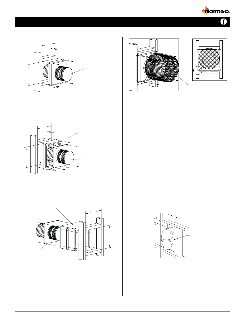
Installing Terminations with Built-In Frames
Installing Terminations with MSR Frames
1. Frame the termination opening to 12" x 12".
2. Fasten the termination to the studs using a minimum of 4 screws.
1. Frame the termination opening to 11" x 11".
2. Fasten the termination to the studs using a minimum of 4
screws.
Installing Terminations with MOSR Frames
MOSR
1. Frame the termination opening to 12" x 12".
2. Fasten the MOSR frame to the interior side of the studs using a
minimum of 4 screws.
3. Insert the termination into the MOSR frame as shown here, and
attach by screwing through the four pilot holes in the termination.
MSR
MTO-4F (4"/7")
PTO-3F (5"/8")
MTO-4F (4"/7")
PTO-3F (5"/8")
MTO-4F (4"/7")
PTO-3F (5"/8")
MTKOG (4"/7")
PTKOG (5"/8")
1. Ensure that the two long mounting brackets are facing the bottom
of the termination. (See inset). This will provide more heat protection
at the top of the termination, where temperatures are highest.
2. Attach to the faceplate of the termination using four sheet metal
screws.
Installing Heat Guards over Terminations
Installing The Remote On/Off Wall Switch
The B-Series DV-2's gas valve, located behind the lower trim, may be
connected to a wall switch. The valve will either generate its own power
on a millivolt circuit or draw its power from an AC connection inside
the fireplace, depending on the model of your unit. Use only low voltage
wire, and DO NOT connect any external power to the remote switch.
Refer to Figure 24, 26, or 30 for wiring requirements.
Note: The switch location must not exceed 30' from the fireplace.
Heat Shields
Due to high flue temperatures, heat shields are required on all B Series
DV-2 installations (except those with vertical terminations) at the point
where the venting connects to the termination. With the heat shield, vent
clearances can be maintained at 1”.
Figure 7. RHS8 Installation. (Install by sliding over vent pipe where it
passes through the combustible construction.
11
11
12
12
12
12
1 MIN
1 MIN
1 MIN. Both
sides Typical
RHS8 Heat
Shield