Installation – Montigo B34DV User Manual
Page 8
Page 8
B-Series DV-2 Gas Fireplace
Part No. XG0160 -141231
PEL
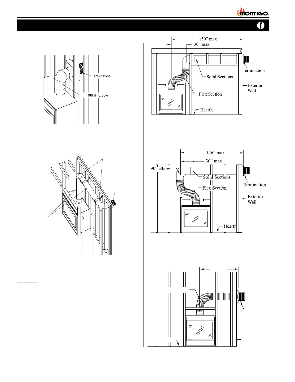
Example 1:
For our shortest venting configuration use components A and E (see
table on page 7).
Figure 9. Typical Top Vent installation. If the 90° elbow is installed
directly on the fireplace, for height to the center of the
termination see chart on page 4.
Horizontal Venting
Figure 10. Typical Top Vent installation. The solid sections can be used
in various combinations to obtain the desired vent run. The
vent run must fall within the limits set by the venting graph.
90° Elbow
MEXT Section
Termination
Example 2:
Rigid sections and an elbow used in conjunction with 3 ft. flex section
(MFL-3) will, when extended in a five foot chase, allow for a maximum
horizontal run of twelve and one-half feet from the centre of the fireplace
to outside wall and a minimum of 7'6" when retracted in opposite direction
(see Figure 11).
"C" flex sections and "D" rigid sections (See table on page 7) may be
used in conjunction with one another to obtain different possible horizontal
length installations, Figure 12.
NOTE: Flex section with no vertical rise must not exceed maximum
horizontal length of 3 feet (see Figure 13). Flex runs over 3 feet must
fall within the limits set by the venting graph, and must have a minimum
vertical rise of 3" per foot of flex.
Figure 11. Extended Installation using a combination of solid and flex
venting. Use the vent graph to determine your allowable
run, then select appropriate components.
Figure 12. Retracted Installation using a combination of solid and flex
venting. Use the vent graph to determine your allowable
run, then select appropriate components.
Figure 13. Horizontal flex installation with no vertical rise.
Installation
36” max.
Flex Section
Hearth
Termination
Exterior
Wall