Dip switch configuration and setting, Installation (cont.), Power supply and field wiring connection (cont.) – MovinCool CM25 User Manual
Page 22
Advertising
22
INSTALLATION (cont.)
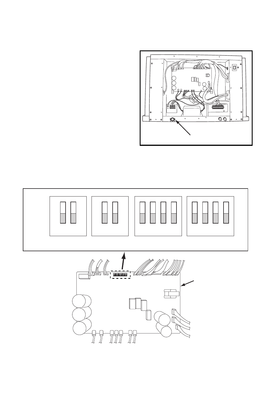
Power Supply and Field Wiring Connection (cont.)
4. Route power cord wires through the
power cord inlet located below
service panel.
5. Connect the line wire (“R” and “T”) to
the terminal block. Tighten screw at
about 0.96 ft•lbf (1.3 N•m) torque.
6. Connect the ground wire (“G”) to the
terminal block. Tighten screw at
about 0.96 ft•lbf (1.3 N•m) torque.
DIP Switch Configuration and Setting
The controller of the unit is equipped with DIP switches, which default in the OFF
position. The DIP switch can be set to configure the following functions.
POWER CORD INLET
RELAY BOARD
ON
OFF
1
2
1
2
1
2
3
4
1
2
3
4
DSW1
DSW2
DSW3
DSW4
Advertising