Nevion FR202 User Manual
Page 17
FR-2RU-20-2
Rev. A
nevion.com | 17
When mounting a backplane, the backplane connector shall always be aligned at the left
and upper corner pin, see figure 13 below.
Alignment pin
+
Figure 14: Alignment pin
If the backplane to be mounted has an EMC gasket of newest type (see fig. 14),
the procedure described below does not apply.
Figure 15: Newest EMC gasket solution
Remove the screws on the back plane to the left of where the new back plane is to be
installed (seen from the back of the frame). Lift the right hand side of it slightly.
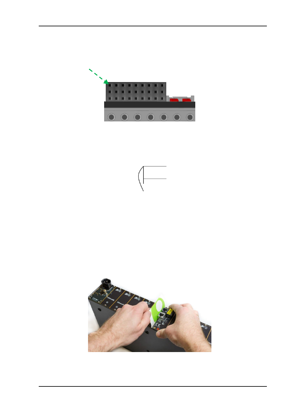
Insert the new back plane. Carefully place the right hand-side of the back plane into the slot
first (this is the side without the EMC shielding.) Then, use your business card (or another
suitable card), and insert the left edge of the back plane as shown in Figure 15 below. This
will help avoid damage to the EMC shield when inserting the new back plane.
Figure 16: Inserting a new back plane.
After the backplanes are mounted, the main module can be inserted as described in
section 5.3