5 psu insertion, 6 psu removal – Nevion FR202 User Manual
Page 22
Advertising
FR-2RU-20-2
Rev. A
nevion.com | 22
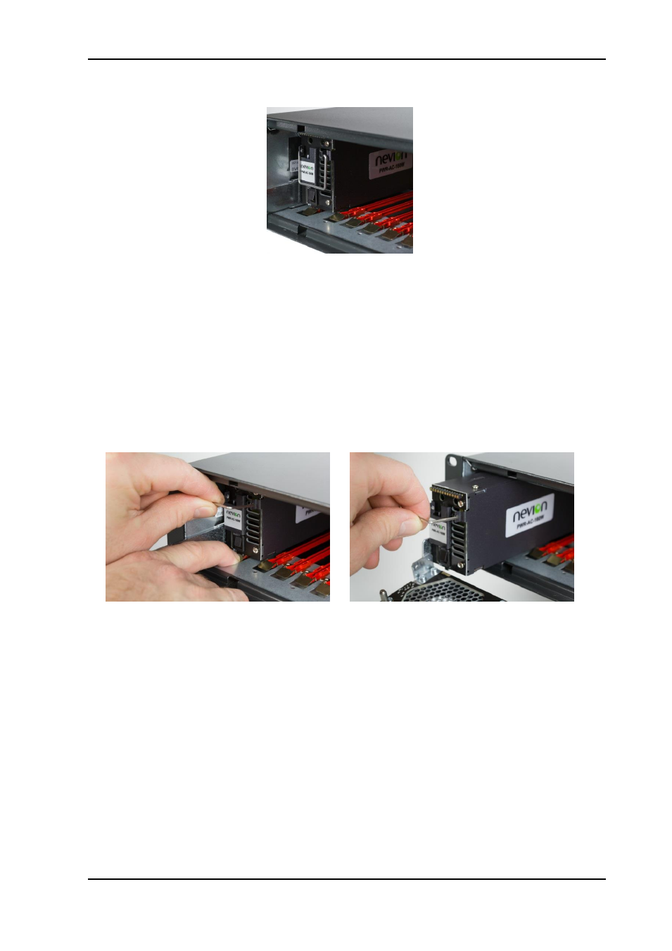
5.5 PSU insertion
Figure 25: PSU insertion.
The outer left and outer right positions are allocated for PSUs.
With exception for the lacking card handle the procedure for mounting is similar to main
module insertion procedure.
In a non-redundant configuration any PSU position may be used.
5.6 PSU removal
Figure 26: PSU removal
To remove a PSU from the frame, push the spring loaded card lock downwards. Be aware
of the PSU connector release force.
Then, simultaneously with the other hand, move the metal handle from vertical to nearly
horizontal position and pull the PSU entirely out of the rack.
Advertising