3 rear view – Nevion FR202 User Manual
Page 7
Advertising
FR-2RU-20-2
Rev. A
nevion.com | 7
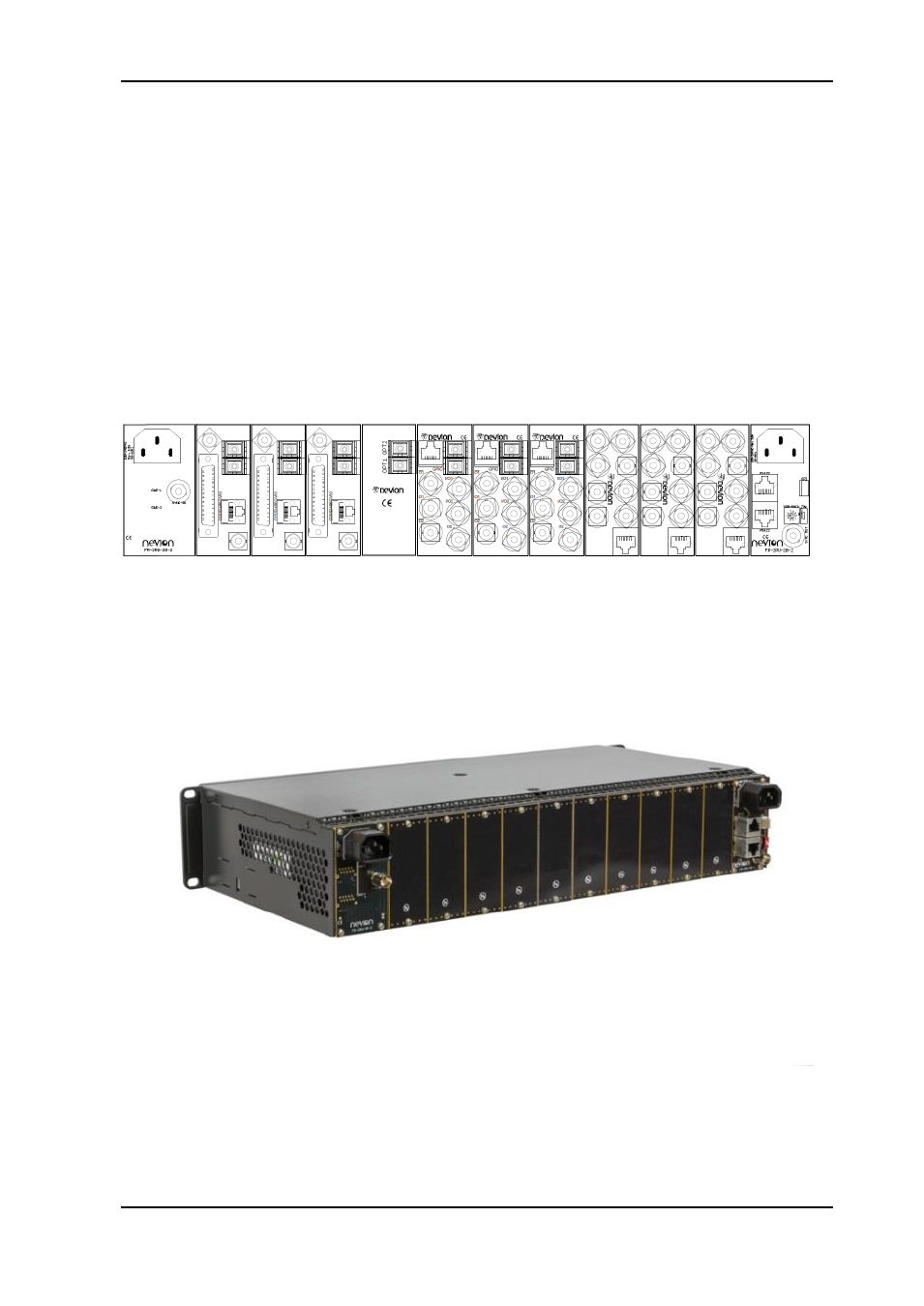
2.3 Rear view
Figure 2 shows an example of a fully equipped Flashlink frame, seen from the rear side.
The outer left and outer right modules are backplanes for the power supplies and contain
connections as follows;
-
Left backplane;
o IEC-C14 AC mains inlet
o BNC, sync in
-
Right backplane;
o IEC-C14 AC mains inlet
o BNC, sync out
o 2pcs. RJ-45 for RS-422 in/out
o Rotary switch for programming frame number to be read by Multicon
o 4 pin connector, GPI out
*The other connector modules are described in their respective user manuals.
Figure 2: Illustration of fully equipped Flashlink frame.
Figure 3: Flashlink frame equipped with blanks.
Advertising