Norsat O3b 5W BUC User Manual
Page 22
Rev. 1.0
7005STC-O3B Series
DES007565
22
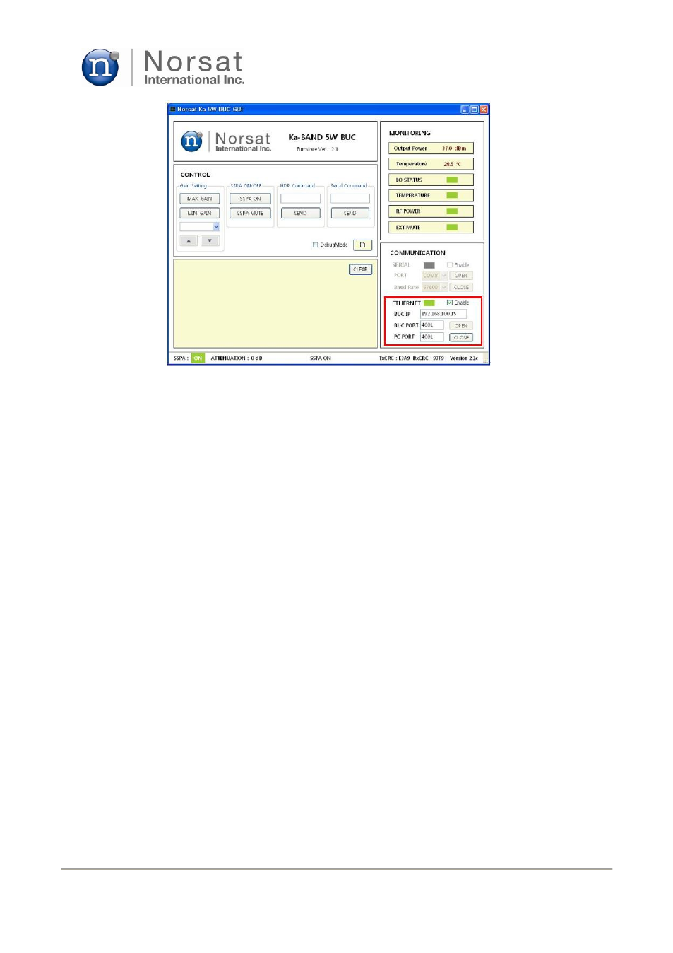
Figure 16. PC parameters entry on BUC GUI window for Ethernet operation
If the Ethernet port is open, BUC GUI will show a serial number (SERIAL NO), and the LED
color for ETHERNET changes from red into green and Enable is marked as shown in Figure
16. BUC GUI starts reading status information of the BUC periodically. And you can send
control commands you want to the BUC by clicking proper tabs such as MAX GAIN or SSPA ON
or entering serial commands into the serial command text box shown in Fig. 13.
5.2.5 BUC Turn-on/off Sequence.
After the user software is installed on your PC, the following sequence can be used to turn on the
BUC.
1) Connect one end of a RF cable with a WR28 waveguide adapter to WR28 RF port on the
BUC and the other end of the RF cable to the antenna or a dummy load.
2) Connect one end of an IF cable to N-type IF connector on the BUC and the other end of the
IF cable to the output of the IF source or modem.
3) Connect one end of a MS 12-wires cable to MS 12-pins connector on the BUC. And
connect two wires out of the other end of the MS 12-wires cable, which are dedicated to
DC power, to a power supply with +48V DC or a level specified in the specification sheet in
Section 3.1, and four wires for Ethernet connection or three wires for RS232 connection
out of the other end of the MS 12-wires cable to the modem or your PC, and two wires for
external Mute function to a separate power supply with +5V on. (Refer to Table 1 and Fig. 4
for connection details)
4) Turn on the power supply to supply +48V to the BUC.
5) Set up the serial mode or Ethernet mode connection according to Section 5.2.3 or 5.2.4.