Interfaces – Norsat O3b 20W BUC User Manual
Page 7
Advertising
2. INTERFACES
2.1
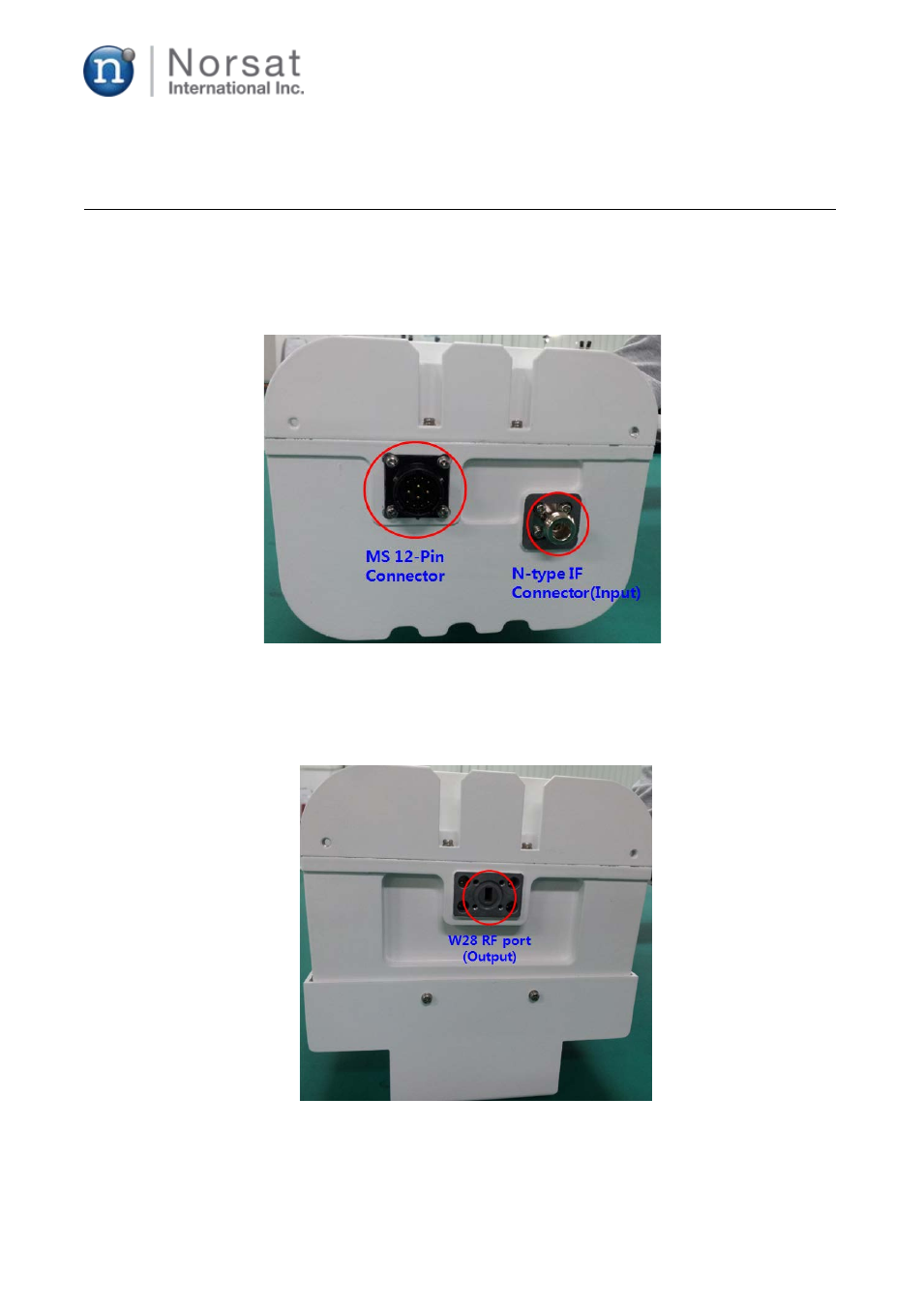
J1 / IF IN
N-type connector is used for the input port as shown in Fig. 2.
Figure 2. N-type IF and MS 12-pin connectors for Ka 20W BUC
2.2
J2 / RF OUT
WR28 waveguide is used for the output port as shown in Fig. 3.
Figure 3. WR28 RF output port for Ka 20W BUC
2.3
J3 / DC, M&C
© 2014 Norsat International Inc.
Page 7 of 25
Advertising