Modbus address, System settings, Status leds – Obvius R9120 Rev C User Manual
Page 8: Signal strength test
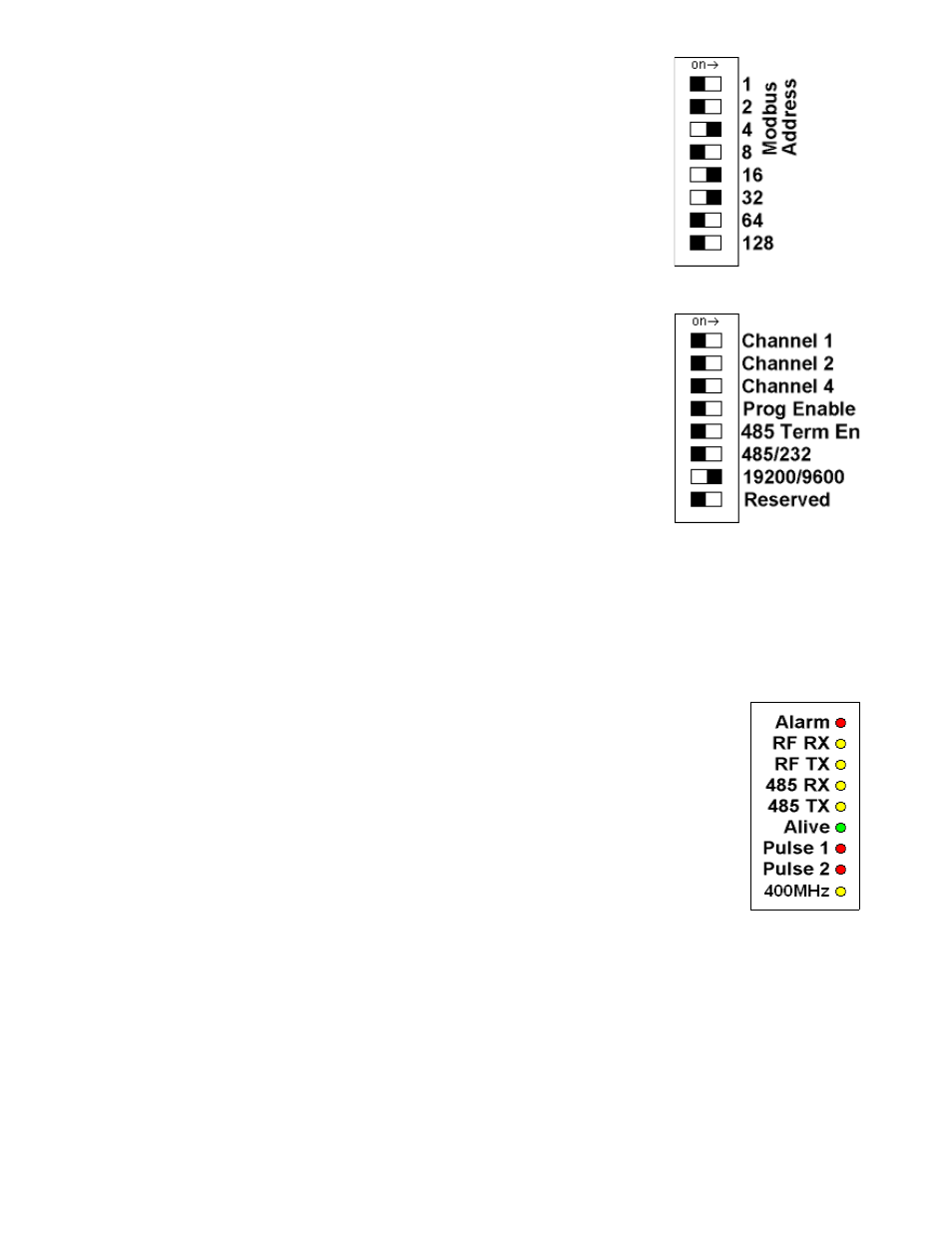
Modbus Address
Before the ModHopper can be used, you must set the Modbus address of the ModHopper.
This address must be unique among all Modbus devices in the system including all devices
that are connected on remote wireless links. Address 0 (all switches off) is not allowed.
Select an address, and set the dipswitches to match.
The sum of the value of the switches is the address. In the example to the right, address 52 is
set by placing switch 4, 16 and 32 to the on position.
Note: 4 + 16 + 32 = 52
System settings
For most systems, set all of the system switches to the "off" position.
Radio channel: This option selects the channel number that can be used to isolate a group of
ModHoppers. This option may be set for channels 0 to 6. Channel 7 (all 3 switches on) is not
allowed.
Programming: Set the “Prog Enable” to Off for normal operation.
485 Termination Enable: Set the “485 Term En” to ON to enable a 120ohm termination
resistor on the RS485 network. This should be used when the ModHopper is on the end of a
485 wiring run. Set this switch to OFF when the ModHopper is in the middle of an RS485
wiring run.
Port RS232 or RS485: Set the switch to the “off” position for RS485 operation. The
ModHopper can communicate via the RS232 connection however most Modbus devices will need 485 terminals. .
Baud Rate: This option sets the serial port speed for the Modbus devices connected to the ModHopper. Set this option to
“off” for 19200. Set the switch to “on” for 9600 baud.
Reserved: Set this option to Off.
Status LEDs
The device should power up and be ready in a few seconds. The LEDs should blink in the following
manner.
●
The "Alive" LED should start to blink about once per second.
●
The Alarm LED will blink when transmission errors occur.
●
The RF TX/RX LEDs will blink when the radio is receiving or transmitting data.
●
The RS485 LEDs will blink for local Modbus activity.
●
The Pulse input LEDs will light when the corresponding pulse input terminals are closed.
●
If the device has the -SN option, the 400MHz LED will blink when an RF packet from a 400MHz
sensor transmitter is received.
Signal Strength Test
When the ModHopper is operating, the Test Button can be used to report the signal strength received by the ModHopper
from another unit.
Press and hold down the test button. The status LEDs will light up as a bar graph display. Each LED is approximately 10%
of scale. For example if PULSE 1 and 2 are on, the received strength is approximately 20% to 29%.
For useful signal reporting, it is important to turn off all but one other ModHopper. When reporting the signal strength, the
most recent wireless transmission received is displayed. If two ModHoppers are transmitting, the display will only show the
most recently received packet, and the user will not be able to determine which ModHopper the signal strength being
reported.
Page 8
ModHopper R9120 rev C – Wireless Modbus/pulse transceiver