Monitoring usage, Acquisuite data display page – Obvius R9120 Rev C User Manual
Page 9
Note: the normal operation of the ModHopper is suspended while the test button is pressed. Modbus communications and
wireless transmissions are not processed.
Monitoring usage:
The ModHopper has several data points that may be read using the Modbus protocol.
For each of the two pulse inputs, the ModHopper reports a value for consumption and rate. Rate fields are provided for the
average rate during the log period (block demand), the instantaneous rate, and the min/max instantaneous rate observed
during the log period. The pulse counts for each input are stored in non-volatile memory to preserve the count when power
is removed. For more information on the specific Modbus registers used for the pulse inputs, refer to the Modbus register
section of this manual.
When configuring a Modbus Master such as a PLC, TCP Gateway, or computer software, you must increase the timeout on
the RS485 port of your system. The ModHopper adds about 500mS of delay per hop. In a complex system with multiple
ModHoppers, a 1 to 2 second round trip time is not uncommon.
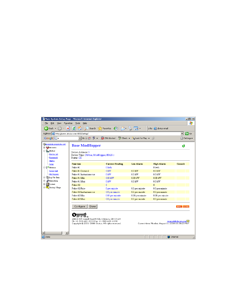
AcquiSuite Data Display Page:
When using the ModHopper with the AcquiSuite data acquisition server, the AcquiSuite will read the pulse input data from
the ModHopper and provide configuration menus for all of the ModHopper options.
The AcquiSuite will display will report all the data values present on the ModHopper. In addition, the instantaneous
min/max rate values will be cleared after each logging interval. Click the Configure button to set up pulse input names,
unit of measure and multipliers as needed.
Page 9
ModHopper R9120 rev C – Wireless Modbus/pulse transceiver