OnLine Power Signal Saver IPC User Manual
Page 56
6002-1842 Rev A ECO# 8881
46
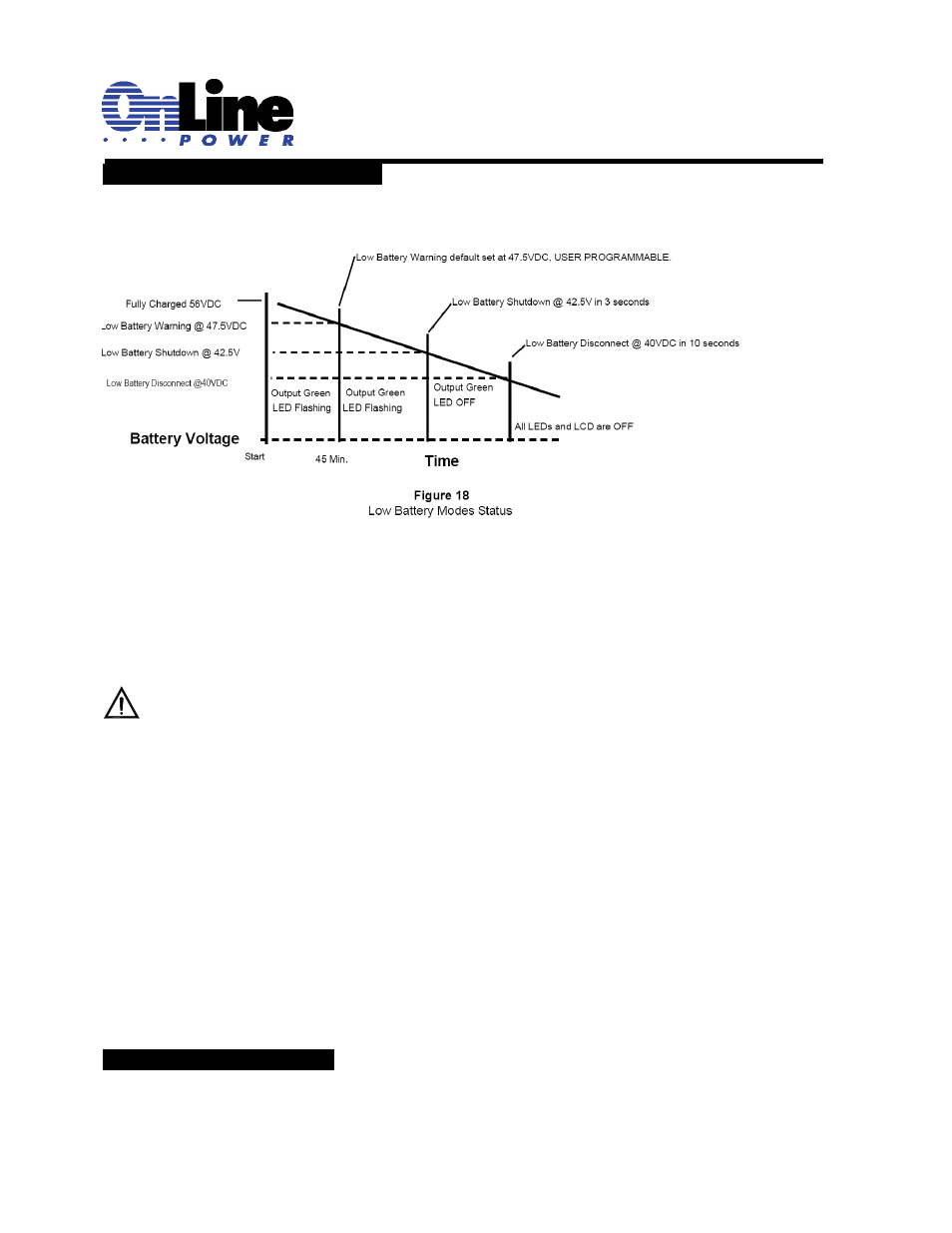
2.2.17 Low Battery Mode Status
Purpose: Describes the various states of the Low Battery Mode (Figure 18).
Note: Not to scale. All values are shown for illustrative purpose only and will charge under different operating
and battery conditions. Actual times will be different. Perform a Battery Backup Time Test (Section 2.4.1) for
your operating conditions.
Low Battery Warning
The Batteries still power the loads, but they are almost discharged and cannot power them much longer.
TIP: The operator should shut down unnecessary loads to extend battery backup time.
Low Battery Shutdown
When the battery decreases to 42.5VDC for 3 seconds, the unit automatically shuts output OFF. The LCD display will
show STANDBY. The batteries are considered fully discharged and can no longer power the load, but they have
enough power to keep the unit’s monitoring, control and communications (RS232/USB) circuits active. This
housekeeping power supply is kept on. The unit will return to normal operation automatically and begin battery
charging when AC power returns.
Low Battery Disconnect
When the housekeeping load further drains the battery to 40VDC for 10 seconds, the unit automatically shuts down
completely. It should take a week or more from low battery shutdown for the housekeeping loads to drain the batteries
to this point unless the batteries are damaged or there is a short or other parasitic load on the DC circuits. The
batteries are disconnected from the unit to protect them from damage via deep discharge. Both the LED and LCD shut
OFF, showing the unit is shut off. The unit stays off until line power or a backup generator is available or fresh batteries
are connected. The unit will restart automatically and begin battery charging when AC power returns. If the system is to
remain off for more than a short time, to prevent battery damage, the AC Input/Output and battery circuit breakers
must be switched OFF and the Manual Bypass switch must be switched to the Bypass position. For additional
protection disconnect the Anderson battery connector from the BBS.
2.2.18 Parameter Changes
All parameter changes should be performed by authorized personnel as it will affect the performance of the traffic
intersection.