Troubleshooting – Orion System Full Digital Module User Manual
Page 12
Full Digital Module
Technical Guide
12
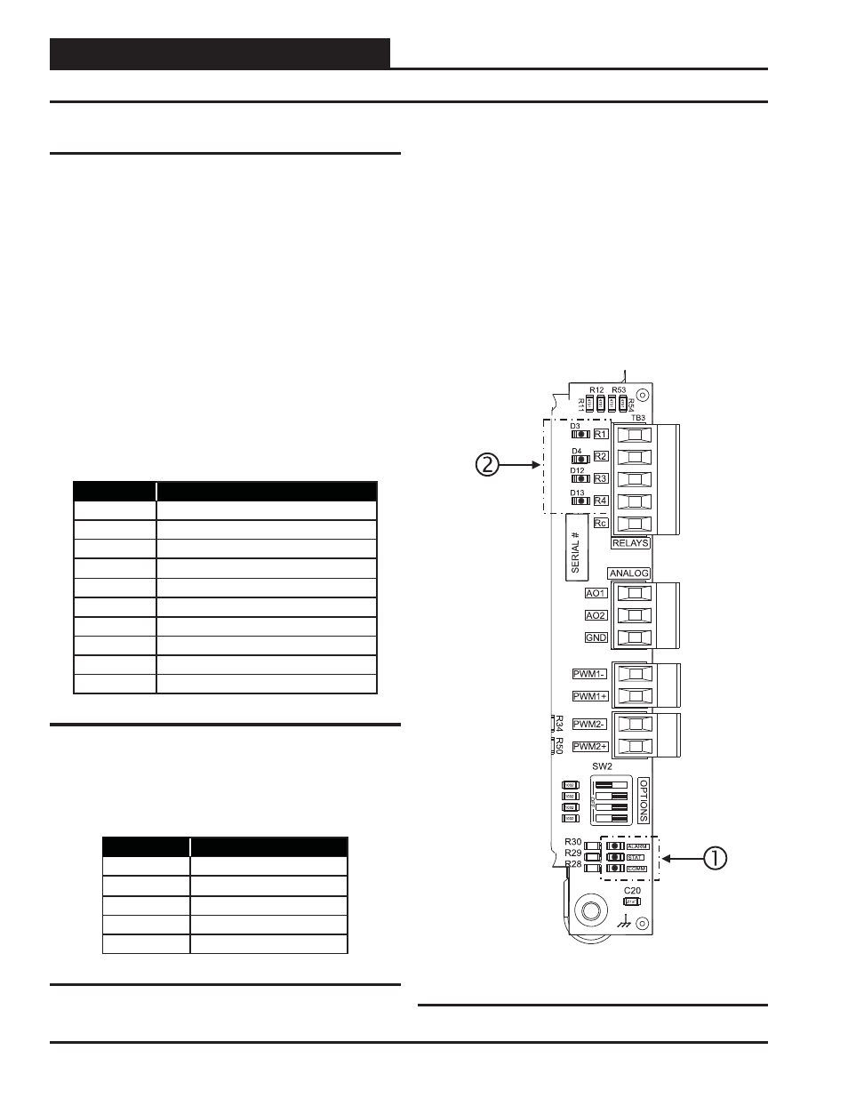
Using LEDs to Verify Operation
The Full Digital Module is equipped with LEDs that can be used to verify
operation and perform troubleshooting. There are LEDs for communi-
cation, operation modes, and diagnostic codes. The module has seven
LEDs—one used for power, one used for operation status, one used for
alarms, and four used for the compressor relays. See Figure 6 for the
LED locations. The LEDs associated with these inputs and outputs al-
low you to see what is active without using a voltmeter. The LEDs and
their uses are as follows:
Status LEDs
“COMM” - The COMM LED lights up to indicate Communications
between the module and the VCM-X Modular series controller. If Com-
munications are established, the COMM LED will blink.
“ALARM” - This is the diagnostic blink code LED. It will light up
and blink out diagnostic codes. See Table 2 for Diagnostic Blink Code
descriptions. The blink code descriptions are also located on the mod-
ule’s front cover.
No. of Blinks
Status
0
No Problems
1
Low Suction Pressure Compressor A1
2
Low Suction Pressure Compressor A2
3
Low Suction Pressure Compressor B1
4
Low Suction Pressure Compressor B2
5
Pressure Sensor A1 Not Detected
6
Pressure Sensor A2 Not Detected
7
Pressure Sensor B1 Not Detected
8
Pressure Sensor B2 Not Detected
9
No Communication
Table 2: ALARM LED Blink Codes
“STAT” - This is the status blink code LED. It will light up and every 10
seconds will blink the status mode that the module is currently operating
under. See Table 3 for Status Blink Code code descriptions. The blink
code descriptions are also located on the module’s front cover.
No. of Blinks
Status
1
Off Mode
2
Cool Mode
3
Heat Mode
4
Dehumidify Mode
5
Defrost Mode
Table 3: STAT LED Blink Codes
Compressor LEDs
“R1” - This LED will light up when Compressor A1 is enabled and will
stay lit as long as Compressor A1 is active.
“R2” - This LED will light up when Compressor A2 is enabled and will
stay lit as long as Compressor A2 is active.
“R3” - This LED will light up when Compressor B1 is enabled and will
stay lit as long as Compressor B1 is active.
“R4” - This LED will light up when Compressor B2 is enabled and will
stay lit as long as Compressor B2 is active.
Figure 6: LED Locations
Troubleshooting