Installation and wiring, Technical guide full digital module 9, All comm loop wiring is straight thru – Orion System Full Digital Module User Manual
Page 9: T to t, r to r & shld to shld, 24vac gnd, G - fan on/off only r - 24vac
Technical Guide
Full Digital Module
9
Installation and Wiring
WARNING: Be sure all controllers and modules are
powered down before connecting or
disconnecting HSSC cables.
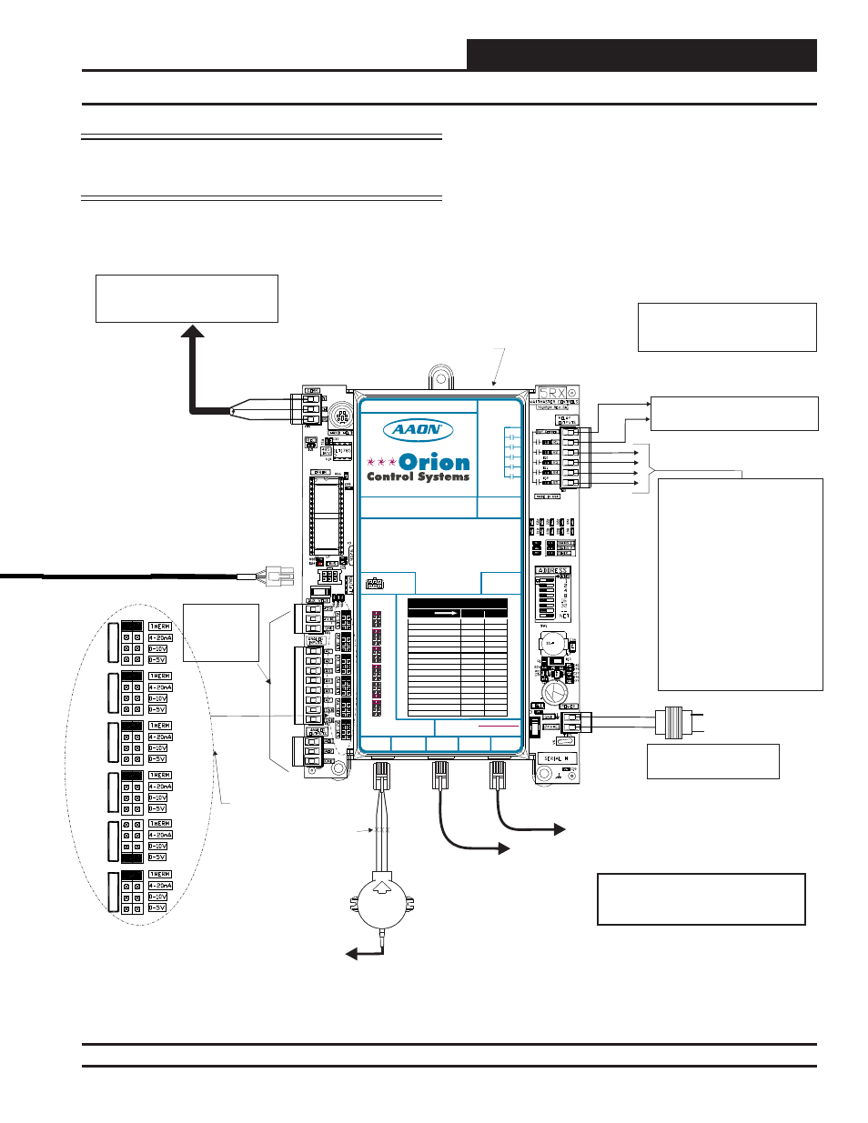
Figure 5, cont.: VCM-X E-BUS Controller to Full Digital Module Wiring Diagram
Line Voltage
All Comm Loop Wiring Is
Straight Thru
24VAC
GND
Local Loop
RS-485
9600 Baud
See Individual
Component Wiring
Diagrams For
Detailed Wiring Of
Analog Inputs And
For Stand Alone Applications,
Connect To System Manager. For Network
Applications Connect To Next Controller
And/Or MiniLink PD On Local Loop.
G - Fan ON/OFF Only
R - 24VAC
Relay Output Contacts
R2 Through R5 May Be User-Configured
For The Following:
1 - Heating Stages
2 - Cooling Stages
3 - Warm-up Mode Command (VAV Boxes)
4 - Reversing Valve (Air To Air Heat Pumps)
5 - Reheat Control (Dehumidification)
6 - Exhaust Fan Interlock
7 - Preheater For Low Ambient Protection
8 - Alarm
9 - Override
10 - Occupied
11 - OA Damper
12 - Heat Wheel
13 - Emergency Heat
Note: 1.) When Using the HP2C Module,
All Compressors Will Be Wired From the
Protection Module, Not the VCM-X Controller.
Note: A Total Of 20 Relays Are Available By
Adding Relay Expansion Modules. All
Expansion Module Relay Outputs Are User
Configurable As Listed Above.
Connect FRP Tubing To High Pressure
Port (Bottom Tube) and Route To Static
Pressure Pickup Probe Located In Unit
Discharge. Leave Port Marked “Lo” Open
To Atmosphere
OE271
Static Pressure
Transducer
Splice If Required
Connect To
Expansion Module(s)
(When Used)
Connect To Digital Room Sensor And/Or
Digital CO Sensor
2
Warning:
24 VAC Must Be Connected So That All Ground
Wires Remain Common. Failure To Do So Will
Result In Damage To The Controllers.
T to T, R to R & SHLD to SHLD
Size Transformer For Correct
Total Load.
VCM-X Modular Controller = 8
OE332-23E-VCMX-MOD-A
VCM-X Modular
E-BUS Controller
Note:
All Relay Outputs Are Normally Open And
Rated For 24 VAC Power Only.
1 Amp Maximum Load.
AI1 SET
AI2 SET
AI3 SET
AI4 SET
AI5 SET
AI7 SET
Jumpers
HSSC Cable Connect To
VCM-X E-BUS Port
RELAY CONTACT
RATING IS 1 AMP
MAX @ 24 VAC
RS-485 COMMUNICATION LOOP. WIRE
“R” TO “R”, “T” TO “T” “SHLD” TO “SHLD”
FAN
RELAY 2
RELAY 3
RELAY 4
RELAY 5
RELAY
COMMON
IC DIGITAL
SENSOR
2
IC
EXPANSION
2
STATIC
PRESSURE
ANALOG INPUT JUMPER SETTINGS
MUST BE SET AS SHOWN FOR
PROPER OPERATION
24 VAC POWER ONLY
WARNING! POLARITY MUST BE OBSERVED
OR THE CONTROLLER WILL BE DAMAGED
AI1
AI2
AI3
AI4
THERM
THERM
THERM
THERM
THERM
THERM
4-20mA
4-20mA
4-20mA
4-20mA
4-20mA
4-20mA
0-10V
0-10V
0-10V
0-10V
0-10V
0-10V
0-5V
0-5V
0-5V
0-5V
0-5V
0-5V
AI5
AI7
ANALOG INPUT
JUMPER
SETTINGS
WattMaster Label
#LB102073-01-A
Rev.: 1A
www.aaon.com
www.orioncontrols.com
VCM-X MODULAR E-BUS CONTROLLER
Orion No.:OE332-23E-VCMX-MOD-A
AAON No.:
V07150
AI1 = SPC (SPACE TEMPERATURE SENSOR)
AI2
AI3
AI4
AI5
AI7
A01
A02
= SAT (SUPPLY AIR TEMPERATURE SENSOR)
= RAT (RETURN AIR TEMPERATURE SENSOR)
= OAT (OUTDOOR AIR TEMPERATURE SENSOR)
= SUCTION PRESSURE SENSOR (FROM EXP. MODULE)
= SPACE TEMPERATURE SENSOR SLIDE ADJUST
OR VOLTAGE RESET SOURCE
= ECONOMIZER (2-10 VDC OUTPUT)
= SUPPLY FAN VFD (0-10 VDC OUTPUT)
LED BLINK CODES
LED NAME
STATUS1 STATUS2
NORMAL OPERATION
0
1
SAT FAIL
1
2
OAT FAIL
2
2
SPC FAIL
3
2
MODULE ALARM
4
2
MECH COOL FAIL
1
3
MECH HEAT FAIL
2
3
FAN PROOF FAIL
3
3
DIRTY FILTER
4
3
EMERGENCY SHUTDOWN
5
3
LOW SAT
1
4
HIGH SAT
2
4
CONT. TEMP COOL FAIL
3
4
CONT. TEMP HEAT FAIL
4
4
PUSH BUTTON OVR
1
5
ZONE OVR
2
5
OUTPUT FORCE ACTIVE
0
6
E-BUS
CONNECTOR