Main screen functions, System manager settings, Smts technical guide – Orion System OE392-10 System Manager TS User Manual
Page 17
SMTS Technical Guide
Main Screen Functions
17
System Manager Settings
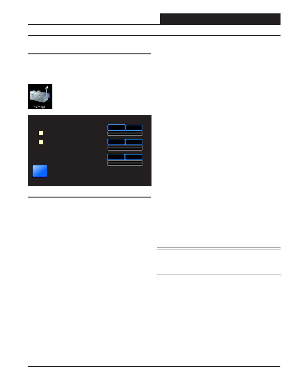
Figure 15: System Manager Settings Screen
30
System Manager Settings
Backlight Timeout
Backlight Intensity
System Manager Address
Back
30
Minutes
30
50
%
30
63
Alarm Polling Enabled
One to One Unit Connection
System Manager Version: 2.00
System Manager Settings
Additional system settings are available under the
<Settings>
icon.
These include setting the Backlight Timeout, the Backlight Intensity
Percentage, the System Manager Address, Alarm Polling, and One to
One Unit Connection.
From the Main Screen, touch the
< Settings>
icon.
The System Manager Settings Screen will appear. See
Figure 15.
Backlight Timeout: This setting is actually a setting for three separate
functions—Backlight Timeout, Main Screen Timeout, and Passcode
Timeout. To set the Backlight Timeout, enter the amount of time you
wish the screen to maintain the active intensity level after the last touch
pad activity occurs. The High limit is 30 and the Low limit is 0. 0 = No
Timeout. The System Manager TS will return to the Main Screen display
at the same rate as the Backlight Timeout, except that if set to 0, the Main
Screen will display after 2 minutes. The Passcode will timeout at the
same rate as the Backlight Timeout, except that if set to 0, the Passcode
will timeout after 2 minutes and will return to System Secured Setting.
Backlight Intensity Percentage: Enter the percentage of light level
you wish to maintain whenever touch pad activity occurs. The High limit
is 100 and the Low limit is 0.
System Manager Address: Enter the address of the System Man-
ager TS. 0 = Stand Alone Mode. 63 = Network System. 1-60 = Multiple
Managers based on the following defi nitions:
•
Stand Alone
—If your System Manager TS is connected to one
controller and you are not using a CommLink or MiniLink any-
where on the loop, your system is Stand Alone. If your System
Manager TS is connected to more than one controller daisy-chained
together and you are not using a CommLink or MiniLink anywhere
on the loop, your system is Interconnected. If you have either a
Stand Alone or Interconnected system, you must enter
<0>
for
Stand Alone Mode. In order to view all controllers on an Inter-
connected System, make sure that One to One Unit Connection,
described below, is not selected.
•
Network—
If you are using this System Manager TS on a com-
munications loop that has a MiniLink or CommLink installed and
you have a single System Manager TS for your entire system, you
must enter
<63>
for Network System.
•
Multiple Managers—
If you are using this System Manager TS on
a communications loop, have a MiniLink or CommLink installed,
and have more than one System Manager TS, then you need to
operate in Multiple Managers Mode. Enter the address
<1-60>
at
which you want this particular System Manager TS to be set. When
more than one System Manager TS is used on a local loop, each
must be set with a unique address different from any other device
on that loop. If you want one of the System Manager TS’s to be
able to indicate alarms for the entire system, you must enter
<63>
for Network System for that particular System Manager TS.
Alarm Polling Enabled: If you wish for the system to poll for alarms,
touch the black box to the left of this item to select it. The box will
turn white and the system will immediately check all loops for alarms.
Touch
<Cancel>
to stop the process. If you wish to have Alarm Polling
Disabled, you must now touch the white box to deselect this option. The
box will return to its previously fully black state.
NOTE:
For the System Manager TS to poll for alarms, you
must also confi gure the unit(s) to poll for alarms on the
MiniLink Polling Device Setpoints Screen using Prism
II. See the Appendix in this guide for more information.
One to One Unit Connection: If your System Manager TS is directly
connected to only one unit, you may wish to select this option to bypass
the Unit Selection Screen and go directly to the unit’s Status Screen. The
controller must be set to address #1 for this to work. Touch the black
box to the left of this item on the screen to select it. The box will turn
white. If you wish to deselect this option, simply touch the box again.
System Manager Version: The version number of the System Man-
ager software appears on the bottom menu bar. This version number is
important to know for troubleshooting purposes.