Electrical connection, Condensation connection, Wiring diagram – REMKO RXW 350 User Manual
Page 15: Rks 435h connections cooling and heating mode
15
Prior to performing any work on the unit, it must
be unplugged from the power supply and secured
against being inadvertently switched on!
Electrical Connection
A power supply line must be installed on the indoor unit
and a control line installed to the outdoor unit.
Included with the units are a two-wire and three-wire
(RXW 350) or a two-wire and four-wire (RXW 480) con-
trol line. If the lines are not used or extended, a five-
wire (RXW 350) and a six-wire (RXW 480) can be used.
All electrical installations may only be performed by
authorised personnel in line with the relevant regulations.
Local guidelines for operation as well as the require-
ments established by local energy supply companies
must be observed for setup and initial operation.
Please observe the following:
◊ We recommend that the customer install a main or
repair switch close to the indoor unit.
◊ Power is supplied to the outdoor unit via a control
line from the indoor unit.
◊ The system’s fuse protection must comply with the
technical data.
◊ The electrical terminals of the connections are lo-
cated on the lower right hand side of the indoor unit.
◊ If a condensation pump, which can be purchased as
an accessory, is used with the unit, an additional re-
lay must be used to increase the switching capacity,
to switch off the compressor, when using the deacti-
vation contact of the pump!
Condensation Connection
Condensation forms on the plate fin exchanger of the
indoor unit during cooling operation because tempera-
tures below the dew point are reached.
The indoor unit is equipped with a condensate collector
and a condensation hose for the condensation that ac-
cumulates.
The condensation hose is connected to the left side
(seen from the front) in this series.
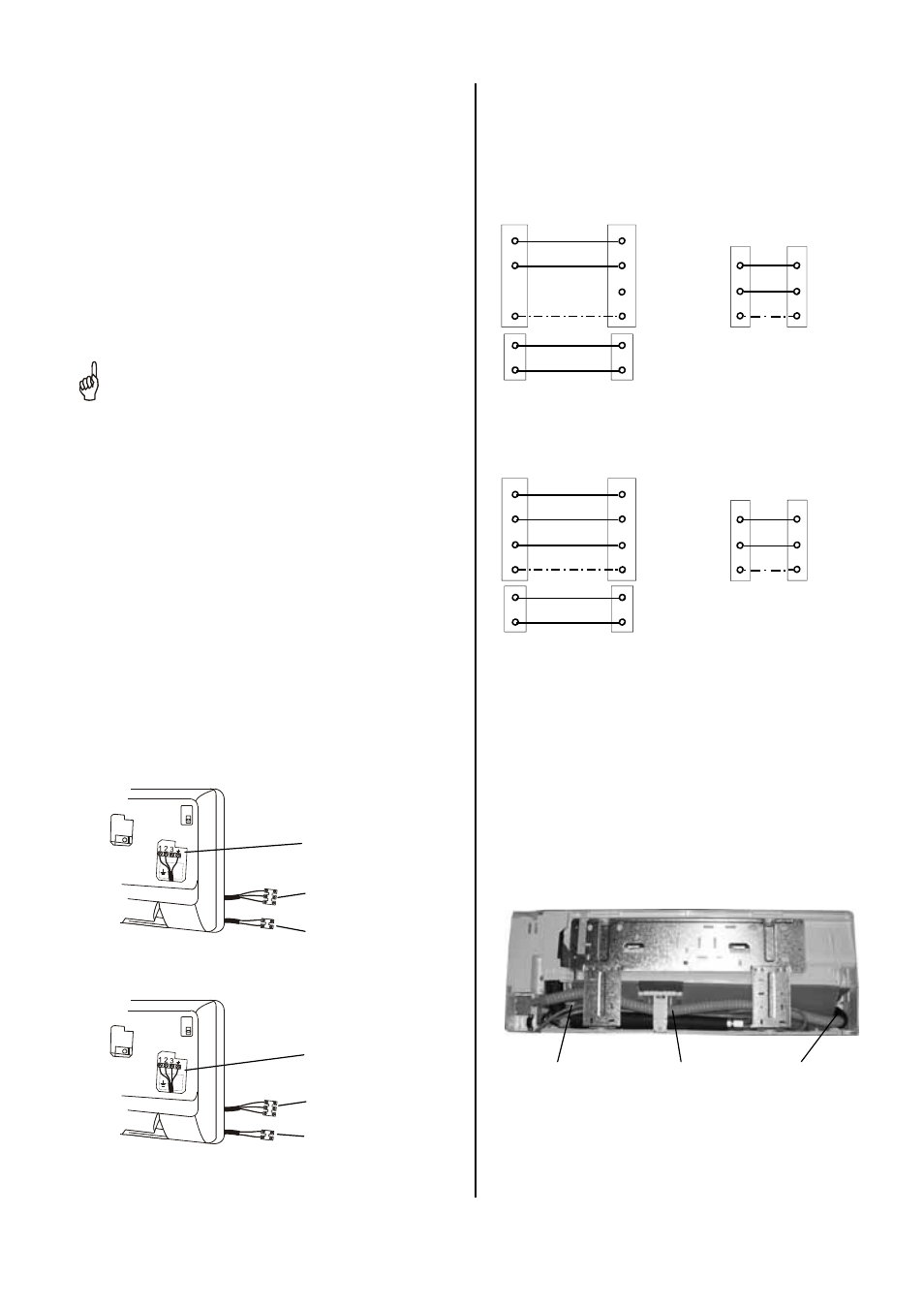
Wiring Diagram
RKS 435H connections
Cooling and heating mode
Outdoor unit
Fan control
Prot. earthing
conductor
Power supply
Indoor unit
2
N(1)
3
2
N(1)
PE PE
Neutral conductor
Compressor control
230 V~,
50 Hz,
L1 / N / PE
Reverse valve control
redd
yellow
N
PE
L1
Phase conductor
red
yellow
N
PE
L1
Outdoor unit
Fan control
Power supply
Indoor unit
2
N(1)
3
2
N(1)
PE PE
Neutral conductor
To the compressor contactor
230 V~,
50 Hz,
L1 / N / PE
Reverse valve control
red
yellow
N
PE
L1
Phase conductor
red
yellow
RKS 448H connections
Cooling and heating mode
RXW 350
RXW 480
Customer-installed connection
line
1. Compressor control
2. Neutral conductor
3. Protecting earthing
conductor
Power supply line
1. L1
2. N
3. PE
Customer-installed connection
line
1. Fan motor
2. Reverse valve
Customer-installed connection
line
1. Compressor contactor
2. Neutral conductor
3. Protection earthling conductor
4. Phase conductor
Power supply line
1. L1
2. N
3. PE
Customer-installed connection
line
1. Fan motor
2. Reverse valve
3
On the right side (seen from the front), there is a sec-
ond condensation hose that is locked into the conden-
sate collector . This connection cannot be used.
Condensation hose can-
not be used
Condensation hose
Condensation connection
to the condensate collector
N
PE
L1
Prot. earthing
conductor