Repair information, Csw45 – Scotsman CSW45 User Manual
Page 22
Repair Information
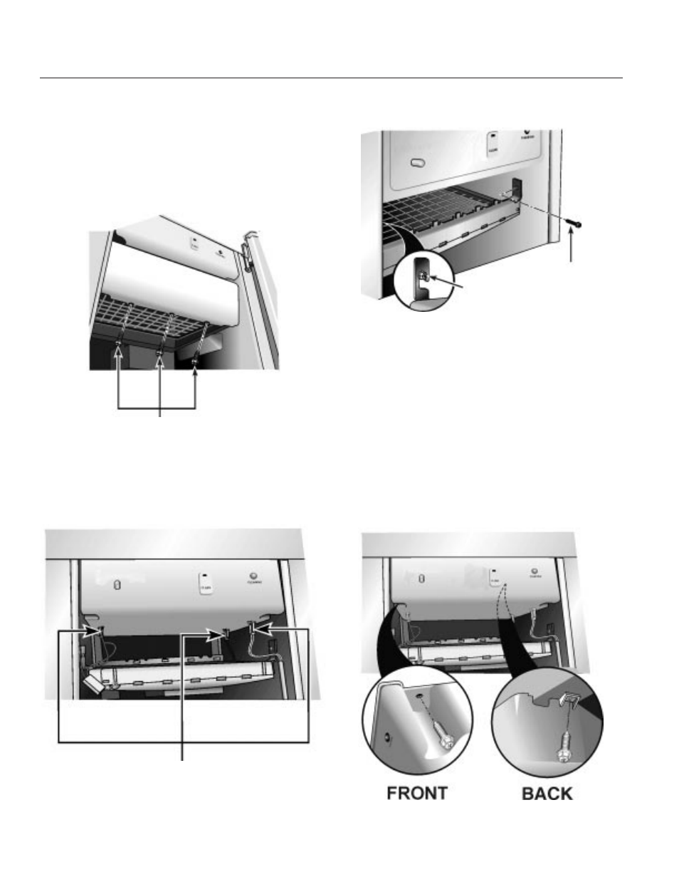
Cutting Grid
The cutting grid rests on two shelves molded into the
bin liner. It is also secured to the liner with two
screws.
1. Remove the three screws holding the cutter grid
cover to the grid.
2. Disconnect the three wiring harness plugs from
the control box.
3. Remove the screw holding the grid to the right
side of the liner.
4. Loosen, but don’t remove the screw holding the
grid to the left side of the liner.
Lift the front of the grid until the slot in the grid clears
the screw, the pull the grid forward and out of the
cabinet.
Control Box
The control box is located above the cutting grid. It is
suspended from the top panel by 4 screws. Its wiring
harness routes out the back of the control box
through a molded channel.
July 1999
Page 22
CSW45
Remove 3 Screws
Wire Harness Plugs
Loosen This
Screw
Remove This
Screw