3 test functions, 2 manual test interface, Earth continuity – Seaward Apollo 500 User Manual
Page 11
This is the Change Format function. This will change the
format of the label
11.2 Manual Test Interface
The Apollo 500 allows direct access to all of the electrical tests through Manual Mode.
Within each test there are a number of function key options;
This is the Tools function. This function allows you to
configure the test current test type, this includes;
- test duration
- test pass/fail limit
- test type/connection
Always ensure that you have selected the correct test
connection method in the test for the probe
connections made.
Please refer to the Test Functions section for specific information about each test type.
11.3
Test Functions
Earth Continuity
Always ensure that the circuit under test is electrically
isolated.
Note that measurements can be adversely affected by
parallel resistances of additional circuits or by
transient currents.
Connecting a test probe to a hazardous voltage when
a point to point measurement is active will result in
that voltage being present on the other test probe.
This test is applicable to Class I equipment. This test will measure one of the following:
resistance between the protective earth terminal in the EUT mains plug and the point at which a single test probe is applied – CLI EUT Continuity
resistance between two test probes – Point to Point Continuity
resistance between the protective earth terminal in an IEC lead mains plug and the protective earth terminal in the IEC connector – IEC Continuity
to ensure that the connection is satisfactory and of sufficiently low resistance. The measurement will be displayed in Ohms.
There are three possible connection methods for the Earth Continuity test.
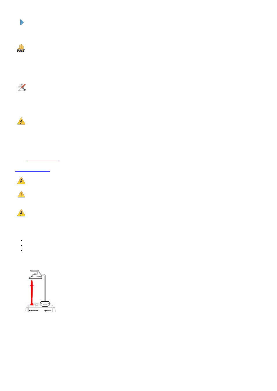
CLI EUT Continuity
The test is performed between the red
test terminal and the EUT test socket.
Point to Point Continuity
This test is performed between the red
test terminal and the black test terminal.