Insulation resistance – Seaward Apollo 500 User Manual
Page 12
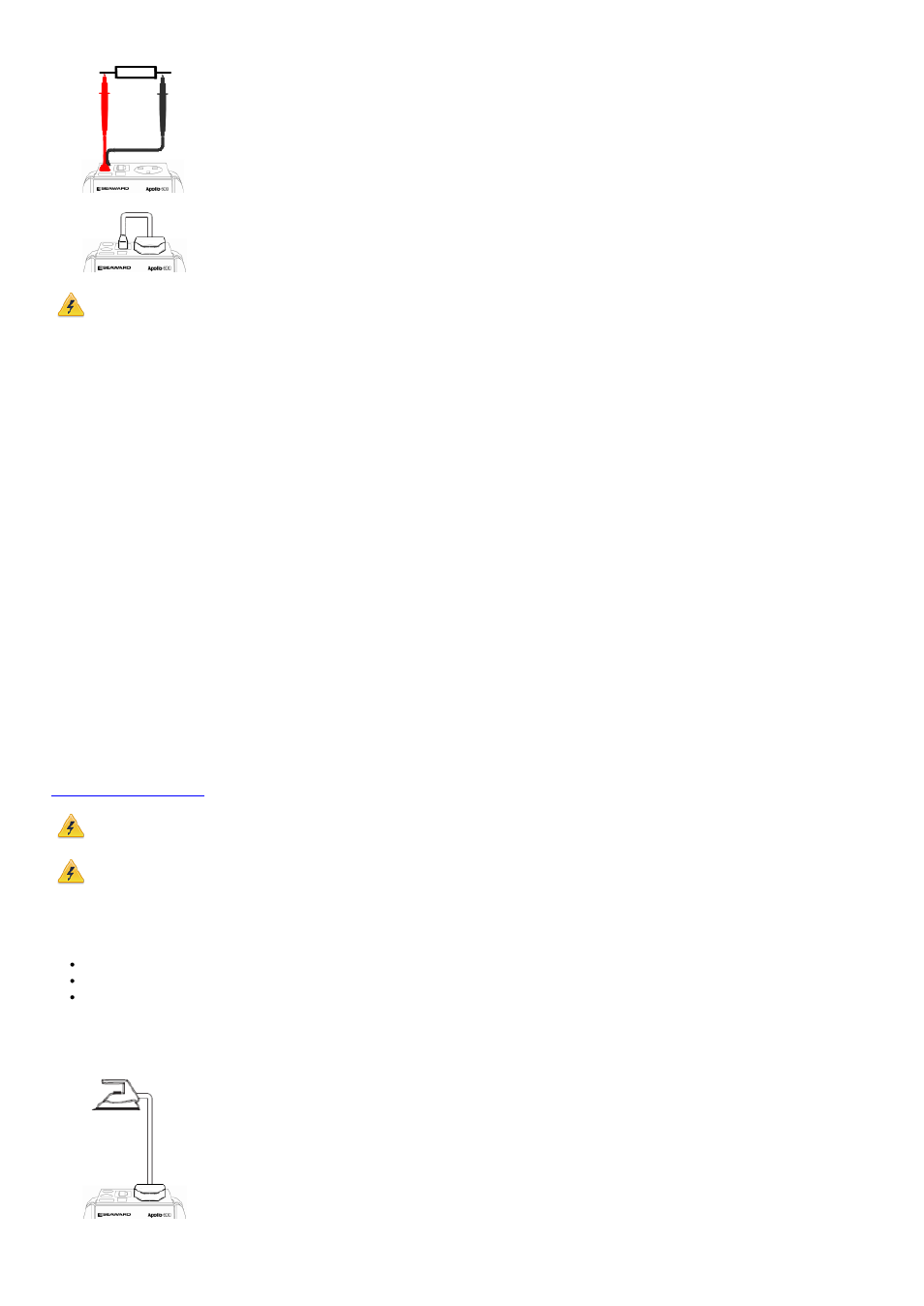
IEC Continuity
The test is performed between the EUT
test socket and the IEC test socket.
Always ensure that you have selected the appropriate
test type for the probe connections.
Selecting test type
In manual PAT test mode, the earth continuity test can be switched between a Class I EUT continuity test and a point to point continuity test as follows:
Select Class I Continuity (1) and press the setup key (F3). In the Test Type field, select EUT Continuity Test or Point to Point Continuity Test.
During automatic sequences, the test type will be as per the test type programmed in the test sequence.
Once the correct connections have been made for the selected test type press the Start button. The test will continue until it times out. If we wish to abort the current test
press the Stop button. Tests on IEC leads, CLI EUTs can be performed using a current of +200mA and/or -200mA. Tests performed in point to point mode are always
performed using a current +200mA test. The direction of the test current can be reversed by switching the test probes at the point of connection to the appliance/circuit under
test.
Nulling out the earth continuity test lead(s) resistance
For a more accurate earth continuity measurement, the resistance of the test lead(s) can be zeroed out. The feature can be used with both the EUT Continuity and Point to
Point measurement modes.
The null facility remains active, even if the Apollo 500 is powered off, until the feature is deactivated by pressing the null key again or the Test Type is changed e.g. if a pair of
test leads are nulled for point to point measurement, the null will be deactivated if the Test Type is changed to EUT Continuity test.
Nulling a single test lead
In the manual PAT screen, press the setup key (F3) and change the Test Type to EUT Continuity Test. Press save (F4). Connect the earth continuity test lead to the earth
continuity test socket and connect the probe tip to the earth pin of the EUT socket. Press Null (F4) to measure and stored the test lead resistance. When the null feature is
active the Null icon will appear on the display.
Nulling both test leads
In the manual PAT screen, press the setup key (F3) and change the Test Type to Point to Point Continuity Test. Press save (F4). Connect both earth continuity test leads to
the earth continuity test sockets and connect the probe tips together using the supplied alligator clips. Press Null (F4) to measure and stored the test lead resistance. When
the null feature is active the Null icon will appear on the display.
Insulation Resistance
Always ensure that the circuit under test is electrically
isolated.
Connecting a test probe to a hazardous voltage when
a point to point measurement is active will result in
that voltage being present on the other test probe.
This test is applicable to Class I and Class II equipment.
This test will measure one of the following:
insulation resistance between live circuits and the protective earth circuit in the EUT – Class I / IEC lead insulation test
insulation resistance between live circuits and a test probe applied to the EUT – Class II insulation test
insulation resistance between two test probes – Point to Point Insulation
to ensure that the test points are adequately insulated from one another. The measurement is displayed in MOhms.
There are three possible connection methods for the Insulation test.
CLI and IEC Insulation
The test is performed between the EUT
test socket live and neutral and the EUT
test socket earth pin.
For IEC leads the other end of the lead
should be connected into the IEC test
socket.
CLII Insulation