Ma3501t – Soundtube MA3501t User Manual
Page 4
Install Instructions For:
MA3501t
MA3501t
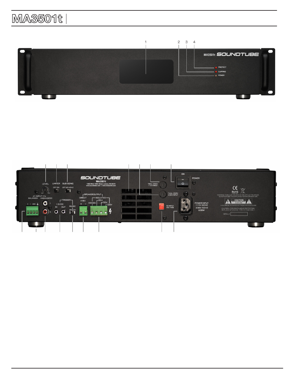
1. Amplifier ventilation inlet and filter -- the opening has a foam filter material that is installed to prevent dirt, dust and foreign material from
entering the amplifier. This filter can be removed for cleaning when necessary and reused. DO NOT BLOCK THIS INTAKE.
2. Power indicator LED -- RED is the power ON in the standby mode, GREEN is ON in the operational mode.
3. Amplifier Clipping LED- normally off, flashing RED indicates amplifier clipping.
4. Amplifier Protection LED- normally off, RED indicates either over temperature or speaker output protection mode.
1. Input Level -- gain adjustment control for setting the amplifier volume.
2. Peak Limiter -- helps prevent signal clipping distortion when the amplifier is used at high output levels.
3. Subsonic Filter – Used to prevent speaker low frequency overload or line transformer saturation distortion due to high power low frequency
levels to the speakers.
4. Amplifier Cooling Vent – Exhaust vent for output of internal cooling fan, DO NOT BLOCK THIS VENT.
5. 230 Volt AC Line Input fuse – This fuse is used only when the amplifier is used in the 230 volt AC line input mode. Replace only with the
same type and size of fuse.
6. 115 Volt Line Input Fuse – This fuse is used only when the amplifier is used in the 115 volt AC line input mode. Replace only with the same
type and size of fuse.
7. Main Power off and on switch.
8. Balance Audio Line Input – This is a removable Euro Block type of connector that is designed for balanced audio input signals and requires
the usage of a 2 conductor shielded audio cable with stripped wire ends. A chassis ground is also provided if needed for your installation
9. Chassis Feet -- Used when the amplifier is to be placed on a shelf and required for proper air circulation through the chassis ventilation
openings. These feet may be removed for rack mounting applications.
10. High Impedance Stereo Input – Dual stereo RCA style input connections that provide high impedance inputs that are mixed to a mono
signal internally in the amplifier.
11. Remote Trigger Input/Output -- This is an input and output loop through 12 volt DC trigger connection for the remote turn on and standby
operation of the amplifier. A 1/8” mono mini phone plug is used for this purpose with the positive connection to the tip and the negative
connection to the ring. When 9-12V DC is present the amplifier will wake up and when power is removed the amplifier will revert to the standby
mode. The main power switch must be on.
Front Panel
Rear Panel
1
2
3
4
5
6
7
8
9
10
11
12
13
14
15
16