Configuration, Configuration – Studio Technologies 214 User Manual
Page 13
Model 214 User Guide
Issue 1, July 2014
Studio Technologies, Inc.
Page 13
can be cut out with a pair of scissors or an
X-ACTO® knife following the printed guide
lines that indicate the required size.
The clear lens on top of each pushbutton
cap can be removed with a fingernail or
small screwdriver. Be certain not to scratch
the pushbutton if a screwdriver or other
small tool is used. The clear label can be
removed and replaced. The cap is then
snapped back into the top of the hous-
ing using finger-pressure only. No tool is
required to replace the cap.
If you need to make your own labels the
process is quite simple. Use a personal
computer to create the desired text. The
finished label size should be 0.625-inches
(15.8 mm) square. The completed artwork
can then be printed on transparency film
sheets using a laser or inkjet printer. These
sheets are readily available from most of-
fice supply stores. A pair of scissors or an
X-ACTO (razor) knife will complete the task.
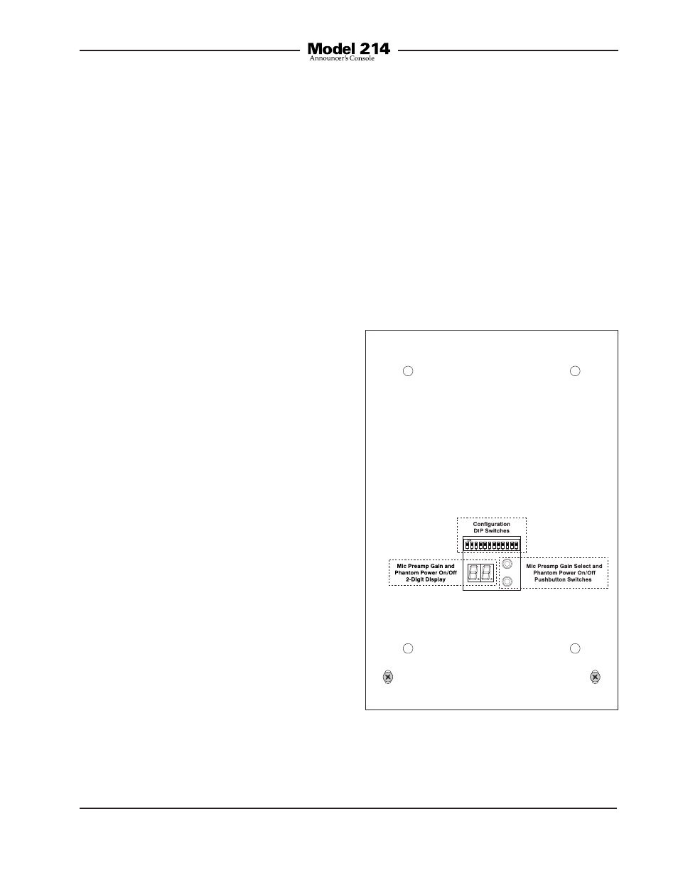
Configuration
For the Model 214 to support the needs of
specific applications a number of operat-
ing parameters must be configured. These
include microphone preamplifier gain,
phantom power on/off, pushbutton opera-
tion, headphone control assignment, and
operating modes. Two pushbutton switch-
es and a 12-position DIP switch assembly
are used to establish the desired configu-
ration. A 2-digit LED display will indicate
the gain of the microphone preamplifier
and the phantom power on/off status. The
pushbutton switches, LED display, and DIP
switches are accessed through an opening
in the bottom of the Model 214’s enclo-
sure. The enclosure does not have to be
disassembled to gain access.
To prevent unauthorized personnel from
changing the configuration settings, a
security panel is attached to the bottom
of the Model 214’s enclosure. For conve-
nience, the security panel provides a sum-
mary of the configurable parameters and
related information. Refer to Appendix A
for a representative view. The security pan-
el is held in place by means of four rubber
bumpers (“feet”) that have built-in screws.
Using your fingers, remove the four bum-
pers so that the panel can be removed.
Refer to Figure 2 for a detailed view of the
configuration switch assemblies.
Figure 2. Bottom view of Model 214 showing
configuration switches and 2-digit display