Operating modes – Studio Technologies 214 User Manual
Page 15
Model 214 User Guide
Issue 1, July 2014
Studio Technologies, Inc.
Page 15
214’s output level. The Model 5202 pro-
vides a 2-channel LED level that is calibrat-
ed in dBFS.
A dual-color LED, located on the back
panel directly below the microphone in-
put connector, is provided as an aid when
using the Model 214. It can also be useful
when setting the gain of the Model 214’s
microphone preamplifier. It provides a
3-step indication of the output level of the
microphone preamplifier. It will light green
when the signal level is –40 dBFS or great-
er, a mix of green and red when the signal
level is –14 dBFS or greater, and red only
when the signal level is –4 dBFS or greater.
When the gain of the microphone preampli-
fier is set optimally a normal signal applied
to the microphone input will cause the
LED to light green with an occasional
“peak” signal causing the LED to light both
green and red at the same time. A more
conservative gain setting would find that
the LED would only light green. A gain
setting that results in the LED ever lighting
only red is incorrect. The gain must be re-
duced or the audio quality will be severely
compromised.
Phantom Power On/Off
The Model 214 can provide P48 (48 volt DC
nominal) phantom power to the connected
microphone. The two pushbutton switches
control whether or not phantom power is
active. Pressing both pushbuttons simul-
taneously will toggle (change) the on/off
state. The decimal point indicator, located
on the lower right corner of the 2-digit LED
display, is used to show the phantom pow-
er on/off status. When the decimal point is
lit phantom power is enabled. By the very
nature of phantom power it should be able
to be left enabled at all times. But generally
people prefer to turn it off unless required
for a specific microphone.
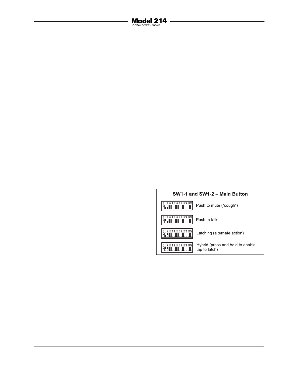
Figure 3. Main button mode switch settings
Operating Modes
Twelve DIP switches are used to configure
the Model 214’s operating modes. Techni-
cally, these switches “talk” to a micro-
controller integrated circuit and associ-
ated software that give the Model 214 its
“smarts.” The software has been carefully
designed to provide a number of different
ways in which the unit can function. It’s
important to carefully review the available
options and choose the ones that best
meet the needs of a specific application.
Note that the switches can be changed
even while the Model 214 is powered up
and operating. The unit’s operating char-
acteristics will change in “real-time” in
response to switch changes.
Main Button Mode
Switches 1 and 2 configure how the main
pushbutton functions.
There are four available modes:
• Push to Mute: In this mode the audio
signal on the main output channel
is normally active. The audio signal
will mute whenever the pushbutton is
pressed and held. This is the “cough”
mode typically used for on-air sports
broadcasting applications.