Studio Technologies 214 User Manual
Page 17
Model 214 User Guide
Issue 1, July 2014
Studio Technologies, Inc.
Page 17
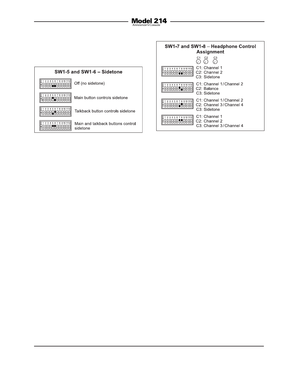
Sidetone
Switches 5 and 6 configure the way the
sidetone function operates.
There are four choices available:
• Audio input channel 1 is assigned to
the left headphone output channel and
its level is controlled by the rotary level
control on the left side of the front panel.
Audio input channel 2 is assigned to the
right headphone output channel and
its level is controlled by the rotary level
control located in the center of the front
panel. Sidetone audio is assigned to
both the left and right headphone output
channels and its level is controlled by
the rotary level control on the right side
of the front panel. Audio inputs 3 and 4
are not used.
• Audio input channel 1 is assigned to
the left headphone output channel and
audio input channel 2 is assigned to the
right headphone output channel. The
overall level of audio inputs 1 and 2 are
controlled by the rotary level control lo-
cated on the left side of the front panel.
The balance (relative level) of both these
signals is controlled by the rotary level
control located in the center of the front
panel. Sidetone audio is assigned to
Figure 7. Headphone control assignment switch
settings
Four modes are available:
• Off: In this mode the sidetone function
not active.
• Main Button: In this mode the sidetone
function will be active whenever the
audio signal is present on the main
output channel.
• Talkback Button: In this mode the side-
tone function will be active whenever the
audio signal is present on the talkback
output channel.
• Main and Talkback Buttons: In this
mode the sidetone function will be
active whenever the audio signal is
present on the main and/or talkback
output channels.
Headphone Control Assignment
Switches 7 and 8 are used to select
the functioning of the three rotary level
controls.
Figure 6. Sidetone switch settings