SVS TL1 110V User Manual
Page 10
8. ELECTRICAL CONNECTIONS
Electrical connections should be made at this time. The TL1 Lift requires 110V/60Hz at .66 Amps and is
supplied with a six foot power cord. The TL1 Lift is controlled with a 24VAC Low Voltage Controller called the
Wall Plate Controller. This controller can easily be connected to external controllers like Crestron, AMX,
Extron, etc. The Wall Plate Controller is supplied with 75-feet of cable (22 AWG, 9 conductor).
Wall Plate Controller Information
Wire Color
Connector Pin Function
Brown
3
Down to Show Position when 24VAC connected from Pin 1
Green
4
Down to Service Position when 24VAC connected from Pin 1
Red
2
Up when 24VAC connected from Pin 1
White
1
24VAC Out (Common) (can be measured between Pin 1 and Pin 7)
Black
7
Power LED Return (Ground)
Orange
8
Power LED+
1. Make sure that the area below the Lift is clear and that all cable are clear of the Lift.
2. Apply power to the Lift by plugging it into an AC Outlet.
3. Before lowering the Lift attach some weight to the bottom of the Lift in order to keep the Lift's cable
tight on the drum until the projector is installed. Both cables are placed on the drum so that they start
unwinding from the outside to the inside of the drum. They are vertical to the eye bolts in the closed
position.
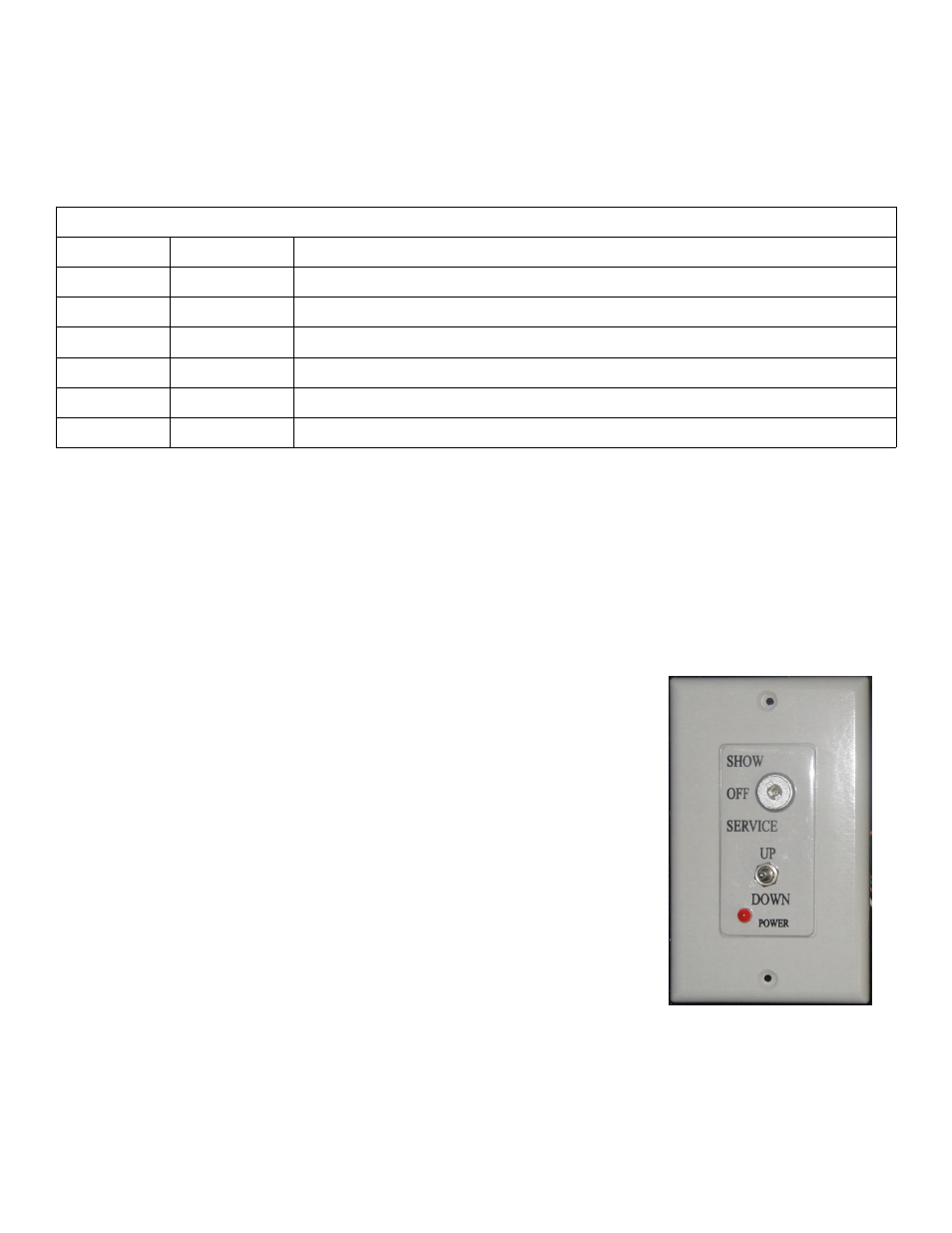
a. How to use the Wall Plate Controller
1. To lower the Lift to the Show position, turn the key switch to the Show
position and press the toggle switch down. The lift will lower as long
as you hold the toggle switch down, the lift will stop when the rear
scissor roller compresses the Show Position microswitch.
2. To lower the Lift to the Service position, turn the key switch to the
Service position and press the toggle switch down. The Lift will lower
as long as you hold the toggle switch down, the Lift will stop when the
rear scissor roller compresses the Down Limit microswitch. The
Service position bypasses the Show Position microswitch.
3. To raise the lift press the toggle switch up. The Lift will rise until the
Up Limit microswitches are compressed. The Lift will rise as long as
you hold the toggle switch up. The Lift can be raised with the key
switch in either the Show or Service positions.
4. The Off position on the key switch disables the Lift.
5. The Power light on the Wall Plate Controller only comes on when the
Lift is raising or lowering (Lift motor turning), not when power is
applied to the Lift.
Important: The toggle switch on the Wall Plate Controller must be pressed to
raise or lower the Lift, releasing the toggle switch stops the Lift. This is
designed as a safety feature. The key switch is an extra precaution, when the
key is removed, the Lift is secured.
SVS TL1 Lift Installation Instructions
Page 10 of 16
Figure 7. Wall Plate
Controller