Component identification – TE Technology TC-24-12 User Manual
Page 12
Advertising
12
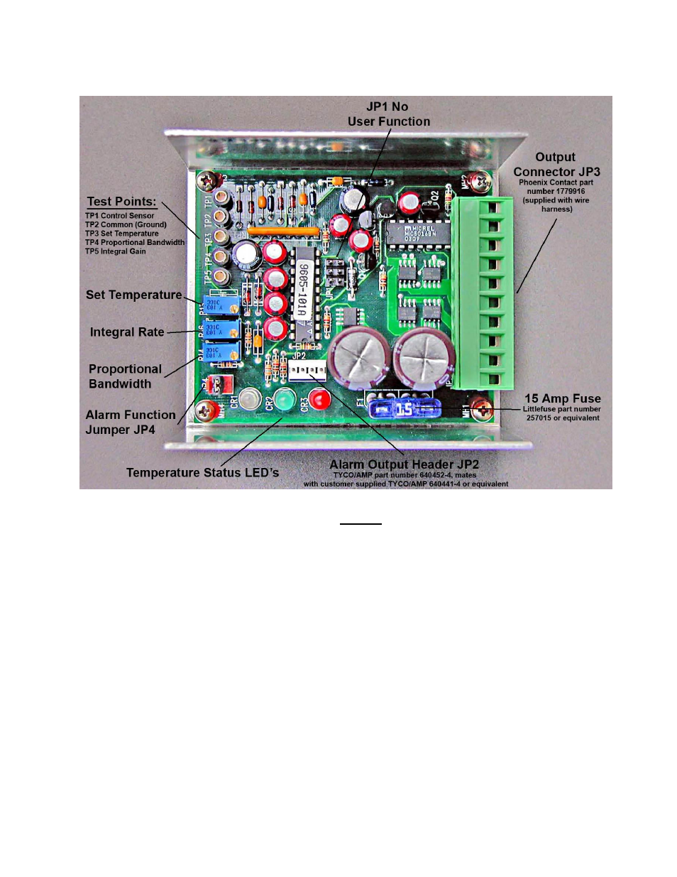
Component Identification
Notes:
Test Points (TPs):
TP1 is the control sensor voltage
TP2 is the common (signal ground) for all test points
TP3 is the set potentiometer voltage
TP4 is the proportional potentiometer voltage
TP5 is the integral gain potentiometer voltage
Potentiometers:
R13 = Set Temperature adjustment (-20 to 100 °C), clockwise to increase
R14 = Proportional Bandwidth adjustment (1.0 to 15 °C), clockwise to
increase
R16 = Integral Rate adjustment (0 to 2.55 repeats per minute), clockwise to
increase
All potentiometers have a 25-turn adjustment range. When the end of the adjustment
range is reached continued rotation of the adjustment screw will result in a faint clicking
sound.
Advertising