Thermo Technologies SMT 400 User Manual
Page 4
SECTION 2 - INSTALLATION
Note: This installation procedure is for guidance only, and its suitability
should be verified by the installer.
2.1
SMT 400 UNIT
NOTES: For viewing comfort, the SMT 400 unit should be positioned at eye
level. It is always good practice to keep electronic equipment away from
cold, and heat, as extremes of temperature may reduce the lifetime of the
device. It is also good practice to keep electronic equipment away from
heavy electrical loads, switches, relays or contactors as these may cause
electrical and electromagnetic interference when switched on or off.
1
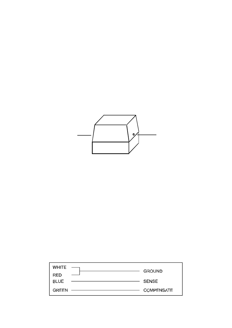
Remove the two side restraining screws as per diagram below, then separate
the TOP controller from the connector BASE.
TOP
SCREW
SCREW
BASE
2
If your cables are to enter the enclosure from behind the unit, then knock out
the appropriate entries in the BASE of the SMT 400.
3
Use the BASE of the enclosure to mark the four corner mounting holes.
Remove the base and drill all necessary holes in the wall or mounting panel.
4
Assemble any grommets or conduit adapters if used, replace the base and
fasten using the four corner screws.
2.2
SENSORS
The SMT 400 is supplied with three sensors (Collector, Return, Tank 1). If
longer cables are needed, sensors are available with extended cable lengths.
Alternatively, sensor extenders are available in a variety of lengths. If the
sensors need to be extended, but factory-made extenders are not available,
they can be extended using a suitable 4 core or 3 core cable, according to
the diagram shown below.
(Note: The SMT 400 is supplied with Tank 2 sensor disabled. A Tank 2 sensor
may ordered separately if required. See section 3.4 for details).
3