Thermo Technologies SMT 400 User Manual
Page 5
Advertising
2.3
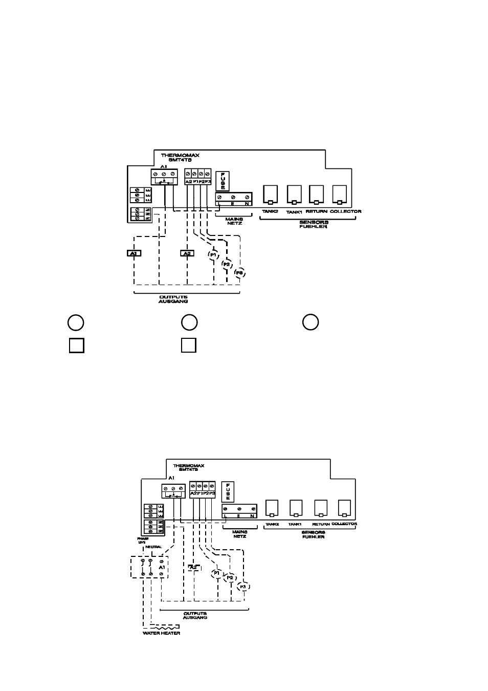
POWER CONNECTIONS AND WIRING DIAGRAM
NOTES: This device should be properly earthed. Flexible wires simplify
connection to the terminals. All connections should be secure and
adequately tightened. It is good practice to keep mains cables away from
sensor cables and other low voltage signal cables.
Connect the mains supply to the unit, as per diagram below:
P1 - Hot Water Pump 1
P2 - Hot Water Pump 2
P3 - Hot Water Pump 3
A1 - Auxiliary Heater 1
A2 - Auxiliary Heater 2
AUX1 + AUX2 :
MAX 3.5A (800W)
PUMP1 + PUMP2 + PUMP3 :
MAX 2.0A (450W)
TOTAL LOAD :
5.5A(1250W)
If the Auxiliary outputs are being used to drive a water heater which has a
greater rating than 800W, then a mains contactor (Relay) should be used as
illustrated below:
4
Advertising