Installation – Tri Tool 236B Single Point User Manual
Page 9
9
Model 236B Single Point
92-1333 : Rev. 110404
INSTALLATION
ATTACHING THE MODEL 236B SP KIT TO THE MODEL 236B
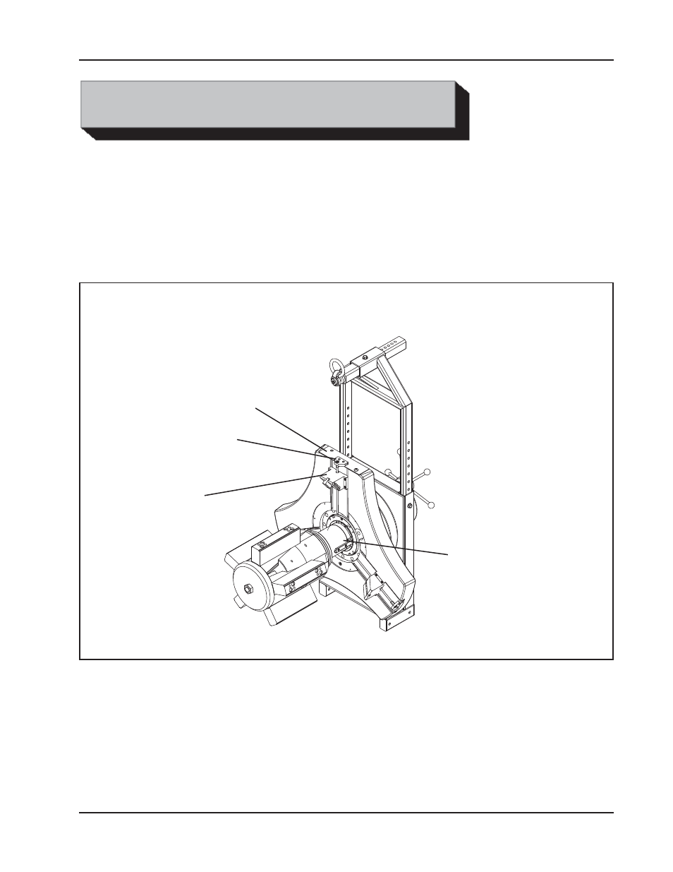
Remove the Mandrel Assembly, Tool Holder Assembly, Adjustment Rod Assembly
and the Cover Plate from the Model 236B Machine.
Secure the Gear (P/N 39-1102) to the Front Locking Plate using supplied flat head
screws (P/N 33-0362).
Secure the Feed Gear Housing Assembly (P/N 82-0226) to the Main Plate, using
supplied cap screws (P/N 33-0043).
Install Plate Assembly, Adapter (P/N 24-2707) onto Main Plate (flat), secure in place
with retained cap screws.
Slide the Cutter Assembly into T-slots on Adapter Plate Assembly to position de-
sired and secure the six (6) cap screws on the base.
Cover Plate
Adjustment Rod
Assembly
Tool Holder
Assembly
Mandrel Assembly
Tool Configuration prior to Single Point installation