Sat iii analog output wiring – WattMaster WCC III part 15 User Manual
Page 20
14. SAT III Controller Installation Guide
WCC III Technical Guide
14-18
SAT III Analog Output Wiring
WCC3 V-Out Relay Board Sequence
There are two modes of operation for the WCC3 V-Out RELAY board. One is the V-Out mode and the other is the Binary Output mode.
The WCC3 V-Out RELAY board has eight relays each with N.O. (Normally Open) contacts. These relay contacts are rated for 1 Amp at 24VAC/VDC operation only.
This WCC3 V-Out RELAY board connects to the HSS expansion port on the side of the SAT III controller. The WCC3 V-Out RELAY board is an expansion board that
Allows for another 8 binary outputs (Relay Contacts) to be used with the SAT III controller. Up to three of these WCC3 V-Out RELAY boards may be connected to the
SAT III HSS expansion port. Two boards in the Binary Output mode are supported, and one board in the V-Out mode is supported. One HSS expansion board will add
10 VA load to the SAT III power requirement.
These eight Analog Input connections must be connected to the eight Analog Outputs of the SAT III controller in the V-Out mode of operation. These analog values are
not digitally transmitted via the HSS port on the SAT III to the WCC3 V-Out RELAY board in the V-Out mode.
There is a load protection device called a varistor across each of the 8 relay output connections of the WCC3 V-Out RELAY board that limit the allowable voltage to no
More than 32 volts AC/DC maximum at 1 amp current draw for each relay output contact. Attempting to switch any voltage greater than 32 Volts or current draws of
more than 1 amp per contact could and will result in damage to the WCC3 V-Out RELAY board and/or to the SAT III controller.
The connecting HSS cable is available in 1 ft., 1
ft., 3 ft., 25 ft., 40 ft., 80 ft., And 120 ft. lengths. No more than 150 ft. of total wire can be used to power a SAT III
½
The Dipswitch on the WCC3 V-Out RELAY board sets the various modes of operation and dead band in the V-Out mode.
Dipswitch SW1-7 (MODE 2 - V-Out Mode) and SW1-8 (MODE 1 - Binary Output Mode) selects the MODE of operation for the WCC3 V-Out RELAY board.
If both MODE (SW1-7 and SW1-8) switches are OFF then the WCC3 V-Out RELAY board is in Binary Output mode. Binary Output 1 to 8 is selected. If MODE 1
Switch (SW1-8) is "ON" then Binary Output 9 to 16 is selected. If MODE 2 Switch (SW1-7) is "ON" then the V-Out mode is selected. You must cycle power to the
WCC3 V-Out RELAY circuit board after setting dip switch SW1-8. You may select any other switch settings without cycling power to the board.
SW1-1 (1) (V-OUT MODE - ADDS 1 VOLT TO DEAD BAND)
SW1-2 (2) (V-OUT MODE - ADDS 2 VOLTS TO DEAD BAND)
(V-OUT MODE DEFAULT SETTING ON)
SW1-3 (4) (V-OUT MODE - ADDS 4 VOLTS TO DEAD BAND)
SW1-4 (8)
SW1-5 (16)
SW1-6 INVERT (V-OUT MODE) (FLIPS CONDITION OF THE RELAY OUTPUTS)
SW1-7 MODE 2 (V-OUT MODE)
(V-OUT MODE DEFAULT SETTING ON)
SW1-8 MODE 1 (When changing this switch, you must cycle power to the circuit board)
Binary Output Mode of operation
When the WCC V-Out RELAY board is set for the Binary Output mode (SW1- switch # 8 is either "ON" or "OFF" and SW1 - switch #7 is "OFF"), the eight relays of
The WCC V-Out RELAY board are controlled by the WCC III program setup of the SAT Binary Output screens for each satellite controller. SW1- switch # 8 "OFF" is
Binary Output board address relays 1 to 8, and SW1- switch # 8 "ON" is Binary Output board address relays 9 to 16. This assumes that SW1 - switch #7 is "OFF".
V-Out Mode of operation
(Hysteresis is added to the Setpoint via setting of the SW1 Dipswitch)
When the WCC V-Out RELAY board is set for the V-Out mode (SW1- switch # 7 "ON"), the relay output will turn "ON" when the input voltage rises above 7.5 VDC
(+/- .25V) plus the dead band setting that is determined by SW1 settings. When the WCC3 V-Out RELAY board is set for the V-Out mode, the relay output will turn
"OFF" when the input voltage drops below 7.5 VDC (+/- .25V) minus the dead band setting that is determined by SW1 dipswitch settings. These dipswitch settings app
for all eight inputs and outputs.
When SW1-1 is selected, 1 volt is added to the dead band. (Dead Band = +/- 1 volts)
When SW1-2 is selected, 2 volts are added to the dead band. (Dead Band = +/- 2 volts)
(DEFAULT)
When SW1-1 and SW1-2 is selected, 3 volts are added to the dead band. (Dead Band = +/- 3 volts)
When SW1-3 is selected, 4 volts are added to the dead band. (Dead Band = +/- 4 volts)
When SW1-3 and SW1-1is selected, 5 volts are added to the dead band. (Dead Band = +/- 5 volts)
The eight analog inputs on the WCC3 V-Out RELAY board must be wired to the eight analog outputs on the SAT III or SAT II controller in order for the V-Out mode to
function. Also, the HSS connector must be connected to the SAT III HSS expansion port for power and ground connections to the SAT III controller or a special two
wire power and ground pigtail must be provided for connection to 24VAC and GND to power the WCC3 V-Out RELAY board.
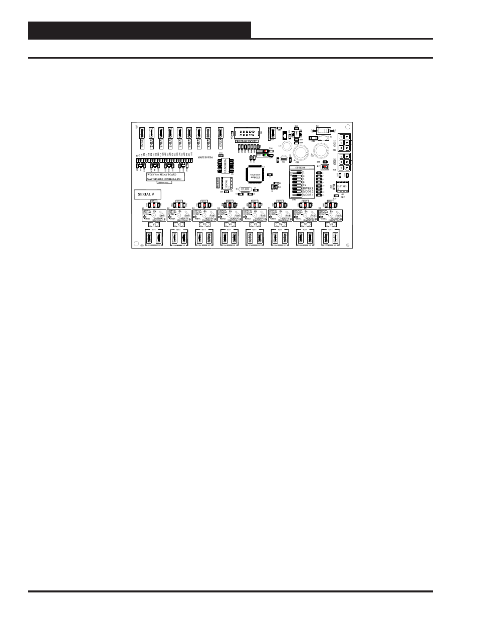
INSTALLATION GUIDE
WCC III V-OUT RELAY BOARD - WITH N/O RELAY CONTACTS
WATTMASTER PART # OE430-01 (SS5008)
HSS loop.