Sat iii, Sat iii introduction – WattMaster WCC III part 15 User Manual
Page 3
14-1
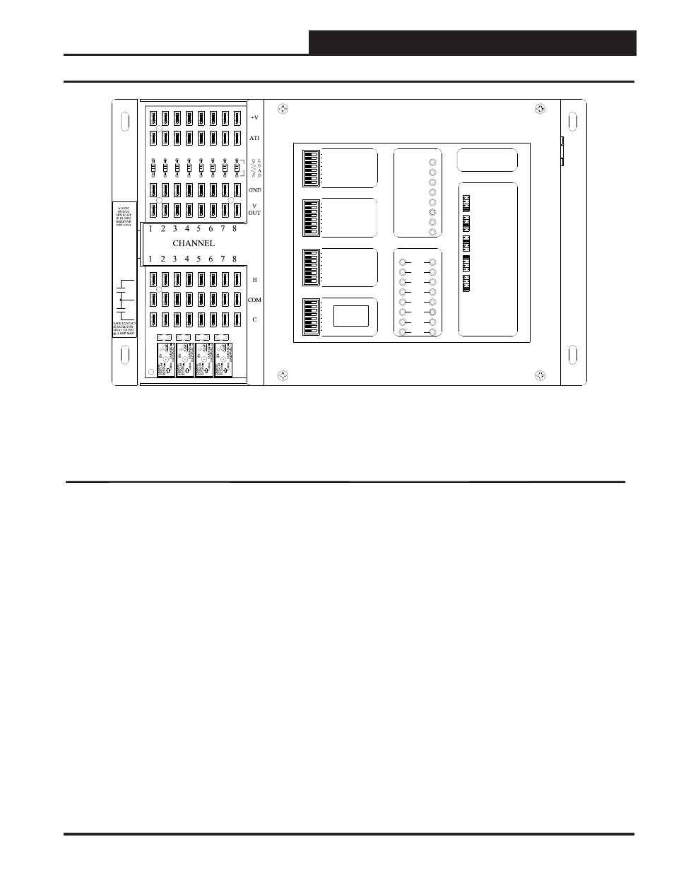
14. SAT III Controller Installation Guide
WCC III Technical Guide
SAT III Introduction
SAT III General Specifications:
The SAT III controller is a drop-in replacement for the older SAT II line of controllers that WattMaster Controls
manufactured from 1983 to 2006. The SAT III is an advanced product improvement over the SAT II controller.
The SAT III features the following:
8 Analog Inputs with 12 bit resolution (The SAT II originally had an 8 Bit A to D converter later upgraded to 10 Bit.)
8 Analog Outputs with 8 bit resolution (The SAT II also had an 8 Bit D to A converter.)
16 Relay Outputs that are Normally Open Relays with varistors for electrical noise suppression. (The SAT II used
expensive "chipswitches" that were low current output, and would only pass AC voltage and they did not have
varistors on the output for electrical noise suppression.)
16 Binary Inputs that are isolated from the microprocessor bus . These Binary Inputs are for use with an external
Binary input board.
(The older SAT II required an Isolation board. The new SAT III does not require a separate isolation board.)
For further details on the SAT III inputs and outputs - See the "SAT III - I/O Specifications" on page 3.
The SAT III communications:
It is a proprietary RS-485 based protocol, and it is based on packetized data in pre-defined parameter blocks.
Troubleshooting of the SAT III RS-485 communications loop is possible with a Digital Volt Meter.
(The SAT II was based on Manchester encoded data and was very reliable but was hard to troubleshoot.)
For the WCC III system, WattMaster Controls has developed a new isolated 485 communication bus that can support
239 SAT III's on four separate communications channels.
A single channel can support up to 60 SAT IIIs on one communications loop. This is for redundant operation. If for
some unknown reason a WCC III communications channel loop goes down, it does not cause other SAT III controllers
on the other loops to lose communications.
8
7
SAT ADDRESS
2
1
4
8
A 3 WIRE ROOM SENSOR WILL NOT
REQUIRE A LOAD RESISTOR WHEN SET
FOR A 1 VOLT INPUT.
WattMaster Controls Inc.
BINARY
INPUTS
BINARY
INPUTS
L8
ON OFF
128
32
16
64
L4
L3
L2
L1
L6
L5
L7
L11
L12
ON OFF
L10
L9
ON OFF
L15
L16
L14
L13
C
H
4
3
5
6
2
1
LOCAL SET
STATUS 2
STATUS 3
STATUS 1
HSS XMIT
LOCAL SET
LOCAL SET DISABLE
BATT ON/ OFF
PULSE INPUT
OPTION 1
TEST
OPTION 3
OPTION 2
ON OFF
STATUS
HSS REC
SAT XMIT
SAT REC
ANALOG INPUT
JUMPER SELECTION
A 2 WIRE ROOM SENSOR WILL REQUIRE
A 300 OHM LOAD RESISTOR WHEN SET
FOR A 1 VOLT INPUT.
A 4 TO 20 mA SENSOR WILL REQUIRE A
50 OHM LOAD RESISTOR WHEN SET FOR
A 1 VOLT INPUT, OR A 250 OHM LOAD
RESISTOR WHEN SET FOR A 5 VOLT INPUT.
CURRENT
INPUT
THERMISTOR
INPUT
0 - 1V
0 - 5V
0 - 10V
THERM
0 - 1V
0 - 5V
0 - 10V
THERM
0 TO 10V
INPUT
0 TO 5V
INPUT
0 TO 1V
INPUT
0 - 10V
0 - 1V
0 - 5V
0 - 10V
THERM
0 - 1V
0 - 5V
THERM
0 - 1V
0 - 5V
0 - 10V
THERM
PROGRAMMABLE CONTROLLER
SAT III
1
2
3
4
5
6
1
2
3
4
5
6
+V SENSORS
R1
R2
1
2
R3
R4
R5
R6
3
4
5
6
C
7
8
C
H
V
OUT
GN
D
7
8
R
R7
R8
7
8
AT
MADE
IN
TH
E
U
S
A
K1
6
K1
5
K1
4
K1
3
V16
V15
V14
V13
SAT III CONTROLLER - OE421-01
INSTALLATION GUIDE (SS5003)