Wavetronix VDR24 Radar User Manual
Page 65
Support, Maintenance, Troubleshooting
VDR24 Radar Detection System, Rev. 1.0
65
Under normal operation the percentage of received and validated messages should always be
100%. If it is not, then the integrity and condition of the communication cables, junction box
interconnections, need to be examined. If the cable is intact and in good condition, and
interconnections are satisfactory, then there may be something related to the radar sensor itself
that requires further examination. In this case contact island Radar engineering and support for
guidance.
9.1.4. Examination of Performance Metrics
The front panel display provides a number of operating metrics to help verify proper operation.
The two key metrics involve and verify proper communication between the VDR24 and the radar
sensors, and proper ‘tracking’ of each of the radars in applications where both radars are
configured to detect vehicles in the same zones, but viewed from different sides of the crossing
(or crossover).
9.1.5. 9.1.5 Detection Levels
In most crossing applications, both radars are configured to detect vehicles in identical zones on
the crossing island, but from different sides of the crossing in order to provide optimal redundant
detection performance. Although both radars will detect each vehicle in the crossing area, the
exact timing or each detection and release will not be identical. Moreover, there are cases
where a particular vehicle may not
precisely occupy a specific lane of traffic,
especially in cases where there is a
turning lane before or after the crossing.
While the exact number of detection
events for each independent radar swill
not be the same, but over time a typical
percentage of “co-incident” detections will
be established for the traffic patterns at a
particular crossing.
This tracking percentage between the
two radar sensors is important because
any physical movement of a radar sensor
will alter its detection zone location – and
cause the typical tracking percentage for
a site to change abruptly.
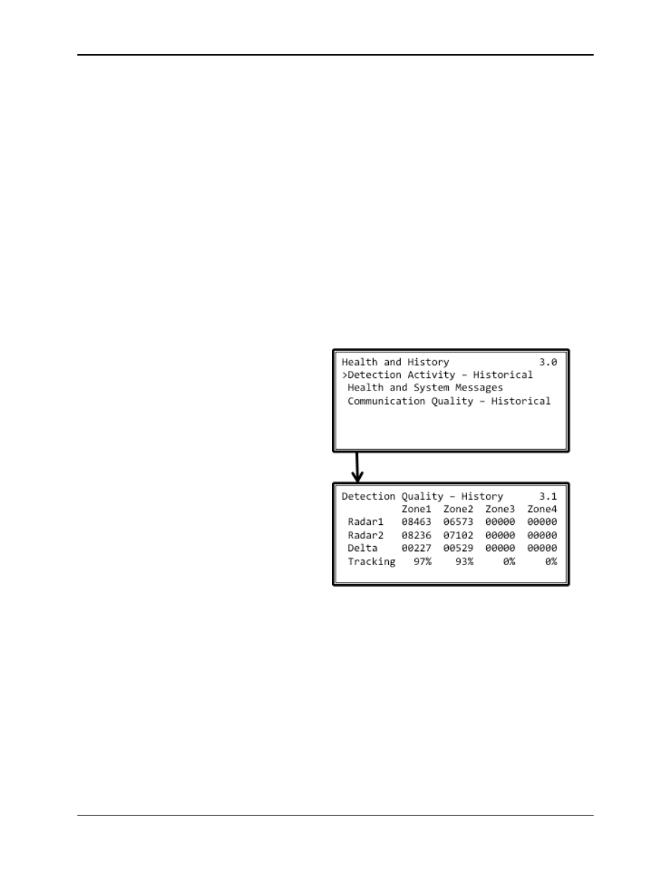
Navigating to screen 3.1 will display the
running total of detections for each radar
and for each zone. Tests have shown
that the two radars, properly configured,
should track each other with a percentage higher that 90%. Any change in physical position can
be identified because the tracking percentage, which should be constant over time, will degrade.
This is an indication that the physical position of the radar sensor and/or the configured zones
should be re-examined as instructed in Section 8 of this document.
9.1.6. Verification of Radar Alignment (Visual)
As instructed during the initial installation of the radar sensors in Section 4.3, verify that the
radar sensors are visually aligned with the roadway, the gates, and exceed the width of the
overall detection area (including all zones).
FFiigguurree 4455 -- C
Coo--IInncciiddeenntt D
Deetteeccttiioonn
M
Meettrriiccss