Wavetronix Click 342 (lean managed ethernet switch) (CLK-342) - Quick-reference Guide User Manual
Installer quick-reference guide, Wire power and communication, Mount the device
Click 340/341/342 Ethernet
INSTALLER QUICK-REFERENCE GUIDE
2
Wire power and communication
Unlike many other Click devices, the Click 340, 341 and 342 do not mount over the T-bus, meaning that
power and communications will have to be wired in. Follow the steps below to install and wire a Click 340,
341 or 342:
1 Attach a wire for +DC (red is standard) to the s 1 crew terminal marked US1.
2 Attach a wire for -DC (black is standard) to the screw terminal marked GND.
3 Attach the other end of these two wires to a DC power source. In a traffic installation with other Click
modules, the best way to do this is to attach a female 5-screw terminal block to the end of the T-bus and
wire the +DC and -DC from steps 1 and 2 into the top two terminal connectors.
4 Make sure the DIN rail is properly grounded, as the Click 340–342 are grounded via a foot that con-
nects with the DIN rail.
˽
RJ-45 jacks (all modules) – Connect an Ethernet cable here
˽
SC fiber optic connectors (multimode: Click 341 / single-mode: Click 342) – Attach fiber optic cables by
pushing the connector down until it engages with a click
www.wavetronix.com
801.734.7200
1
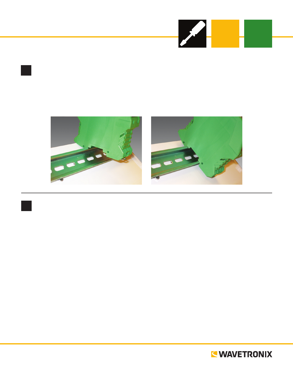
Mount the device
The Click 340–342 mount on a DIN rail. To mount the device, simply hook the lip over the lower edge of the
DIN rail, and use a rocking motion to snap the module into place.
Note. Do not mount over the T-bus.