Wavetronix Click 331 (unmanaged ethernet switch) (CLK-331) - Quick-reference Guide User Manual
Wavetronix Equipment
Click 330/331 Ethernet Switch
INSTALLER QUICK-REFERENCE GUIDE
2
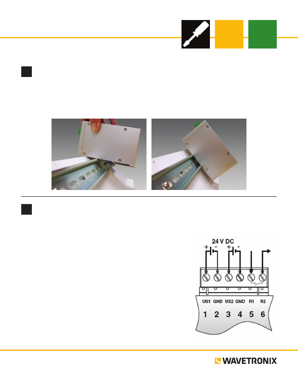
Wire power
Unlike many other Click devices, the Click 330/331 do not mount over the T-bus, meaning that power and
communications will have to be wired in into the device’s six screw
terminals. The first four screw terminals, marked US1, GND, US2 and
GND, are for wiring power. (The other two, which are labeled R1 and
R2, are for security and functionality alarm purposes.)
1 Attach the device to a location on the DIN rail that is not over a
T-bus.
2 Attach a wire for +DC (red is standard) to the screw terminal
marked US1.
3 Attach a wire for -DC (black is standard) to the first screw termi-
nal marked GND.
4 Attach the other ends of these two wires to a DC power source.
Note. US2 and the second GND are for wiring in a redundant power
supply, if you’d like to use one.
www.wavetronix.com
801.734.7200
1
Mount the device
The Click 330/331 mount on a DIN rail. To mount, simply hook the lip over the lower edge of the DIN rail,
and use a rocking motion to snap the module into place.
Note. Do not mount over the T-bus.