Wavetronix Click 100 (16 output contact closure) (CLK-100) - Quick-reference Guide User Manual
Click 100 contact closure
Click 100 Contact Closure
INSTALLER QUICK-REFERENCE GUIDE
www.wavetronix.com
801.734.7200
2
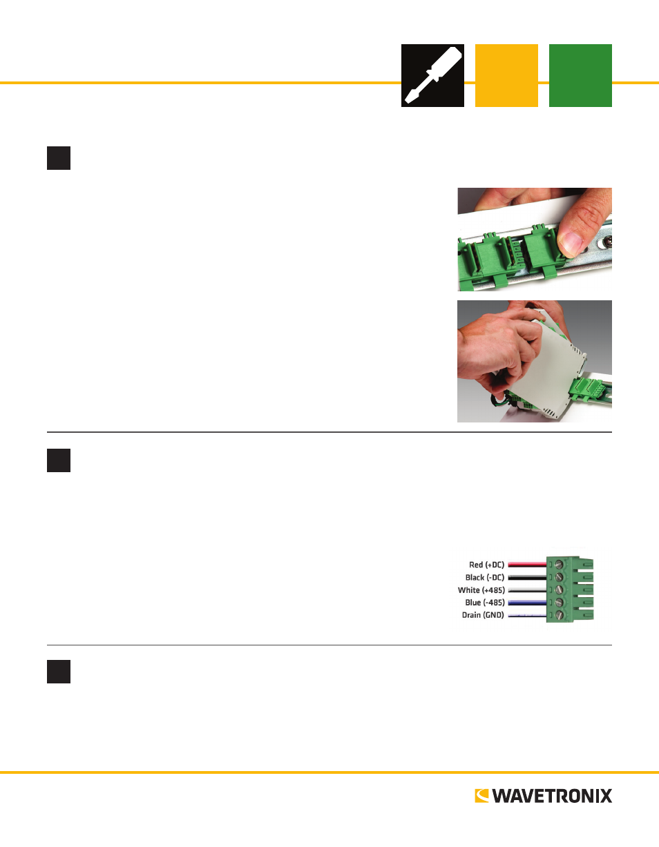
Wire power and communication
If you are using a Click 200 surge protector with the Click 100, power and communication are provided to
the Click 100 through the T-bus (see the Click 200 Quick-Reference Guide). If you don’t have a Click 200
surge protector, use the following steps to wire power and communication into the Click 100:
1 Plug a T-bus 5-screw terminal block into the first T-bus connector.
2 Wire DC power (10–30 V) from the power supply into the first screw
terminal on the 5-screw terminal block; wire -DC into the second
screw terminal.
3 Connect RS-485 communication (+485, -485 and GND) to the re-
maining three screw terminals on the 5-screw terminal block.
3
Use on-device configuration features
Next, use the device’s configuration features. The Click 100 has four LEDs that monitor device activity and
help you select operating modes, as well as a push-button, labeled Mode Switch, also used for operating
modes.
1
Mount the device
The Click 100 mounts over a T-bus for power and communication:
1 If the Click 100 was shipped with the T-bus connector attached, remove
the connector from the module.
2 Snap the connector onto the DIN rail by positioning it over the rail
with the male connector pointing to the right. Hook one arm over the
edge of the DIN rail and press down on the other arm until it snaps into
place.
3 Connect the T-bus connector to the rest of the T-bus by sliding them
together until you hear them snap into place.
4 Mount the Click 100 onto the DIN rail: position it properly over the T-
bus connector, hook the lip over the lower edge of the DIN rail, and use
a rocking motion to snap the module into place.
continued on next page